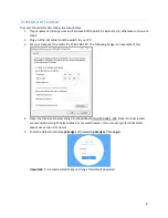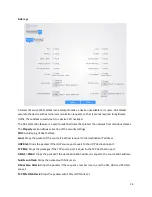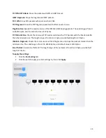
7
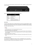
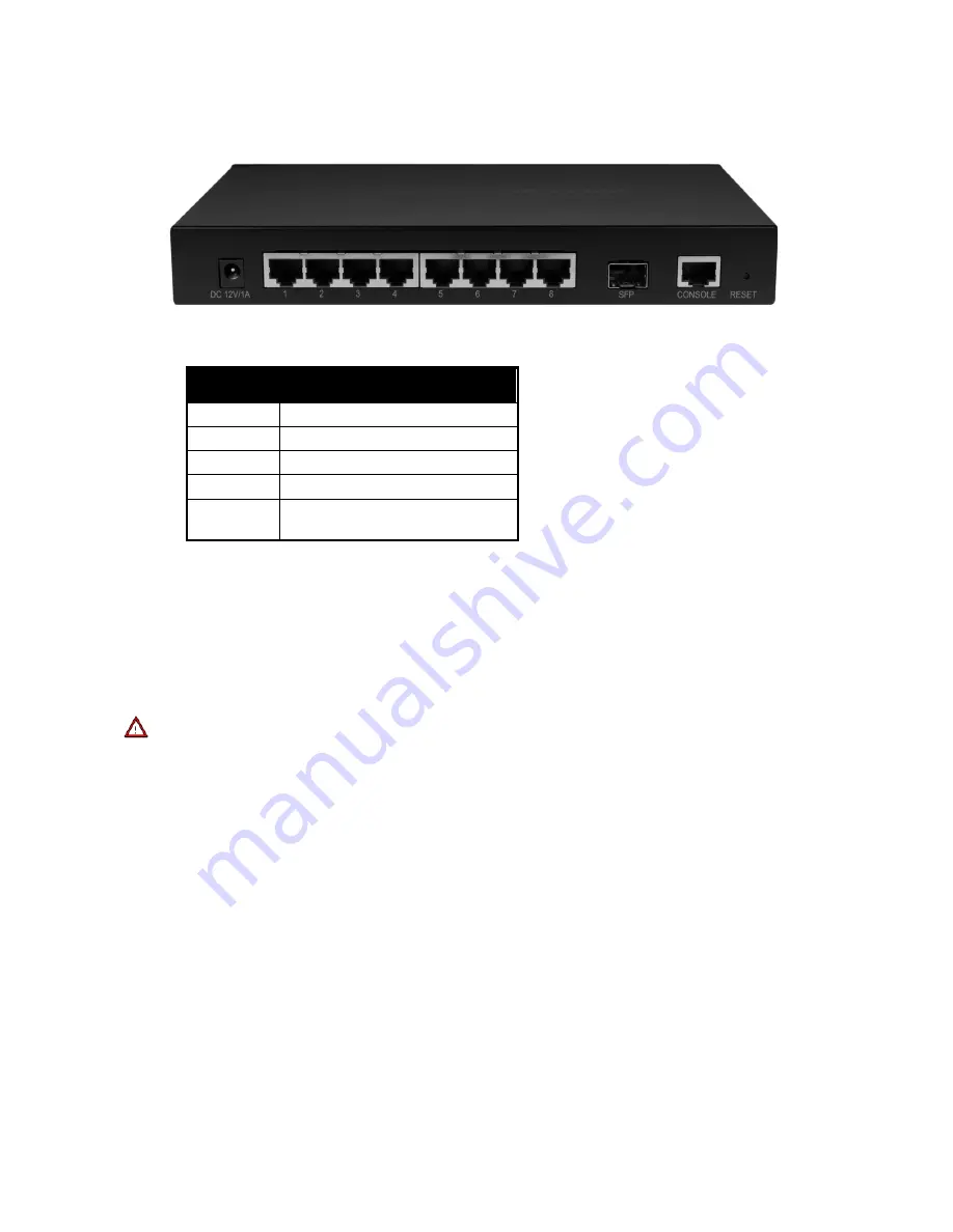
The rear panel of the SX Series switches provides all inputs for a clean installation. See Table 2 below for
more information.
Table 2: Rear panel port connection explanation from left to right.
Input
Description
Power
Power adapter input
Ports 1-8
RJ45 PoE/PoE+ ports
SFP Port
1G SFP port
CONSOLE
RJ45 console port
RESET
Reset button. Press and hold for 10
seconds to factory reset the switch
Reset Button
To restore factory defaults, press and hold the button for more than 10 seconds when the switch
functions correctly. When pressing it for a while, SYS LED will be off and POWER LED is solid. The device
will restart and all LEDs will be on. When there booting finished, SYS LED will be blinking, indicating
restoring to default factory settings.
Note
------------------------------------------------------------------------------------------------------------------------------
1.
Please keep the switch in a dry and well-ventilated environment.
2.
Keep the work bench stable and well-earthed.
3.
Do not restrict airflow covering or obstructing air in lets of the switch. Keep more than 10 centimeters
free on all sides for cooling. Be sure there is adequate air flow in the room or wiring closet where the
switch is installed.
4.
Don’t put heavy articles on the Switch.
5.
Make sure there is more than 1.5 centimeters vertical distance free between devices that stack each
other.
------------------------------------------------------------------------------------------------------------------------------------------
Connecting SFP fiber port
The small form-factor pluggable (SFP) module is a compact, hot-pluggable transceiver used for optical
signal transmission. The module bay is a standalone port, making it the “9
th
” port on the switch. The SFP
module accommodates a standard 1G SFP module with an LC connector.


