29
GTV
FORCED CONVECTION AIR HEATERS
Instructions for Installation and Servicing
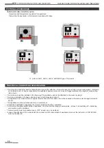
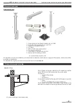
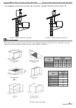
Exhaust system units
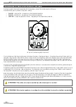
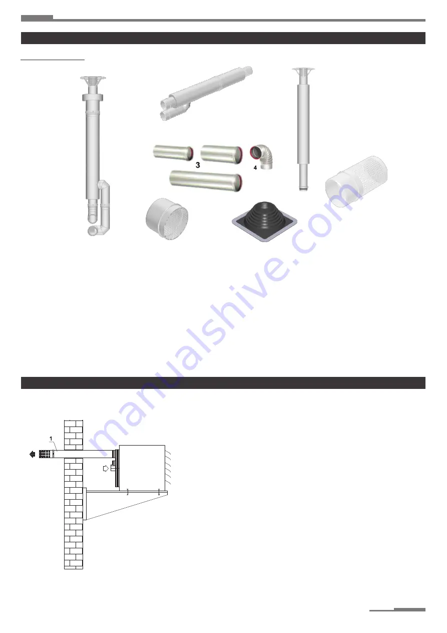
29. picture: Exhaust system units
The appliances can only be installed by such dimensions and material of combustion air supply and flue systems, which are specified
by appliance manufacturer�
The allowable flue lengths and pressure drops can be found in the
enclosure 3�
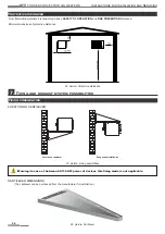
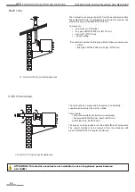
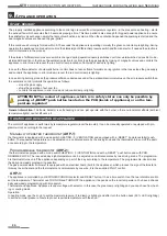
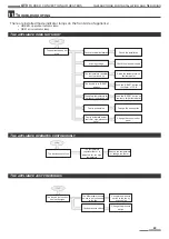
30. picture: B22H type horizontal execution
B22H Type
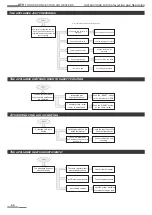
Exhaust systems
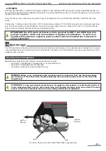
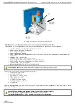
Types of exhaust system
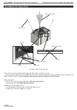
1
2
5
7
6
8
The combustion air supply is directly from the heated area and flue
system Ø100 mm is horizontally across the wall to outside�
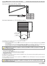
Components:
• horizontal flue terminal
•
clamp
• flue pipe 1 m
It is possible to extend the flue pipe with the following components:
•
clamp
• flue pipe 250/500/1000 mm length (Ø100 mm)
The flue pipe is not insulated for this reason during installation insu
-
lation has to be placed around the pipe between the pipe and wall!
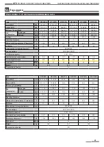
1�
Perpendicular roof exit (flue/combustion air) set C32K
2�
Side-wall exit (flue/combustion air) set C12K
3� Straight unit, 250/500/1000 mm
4� 90° elbow
5�
B23 set for flat roof or side-wall exit
6� Flue end unit B23/C12K
7� Combustion air sucking end unit C12K
8� Rubber bell (for slanting roof B23)

