15
51-3000
ADJUSTMENTS
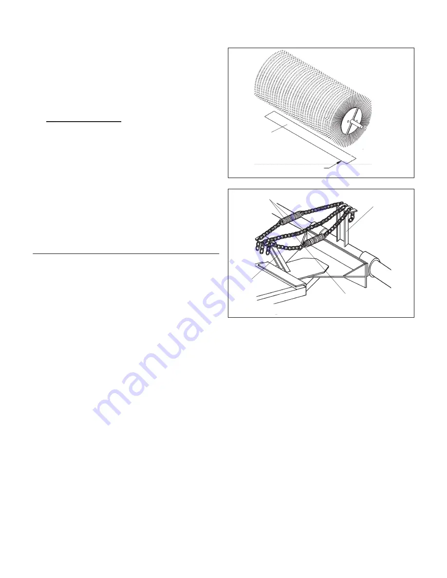
figure 5
figure 6
Spring-Chain
Assembly
Brush Head
Upright
Transport Chain
Drive Assembly
Upright
Swept Area
2-3 Inches
(51-76mm)
the measurements are equal. Tighten the
hardware.
• If they are equal, go to step 6 (2-way
sweepers) or the sweeper is level (1-way
sweepers).
6. 2-way sweepers only - Swing the brush head
assembly to the right. Measure from each end of
the brush frame to the ground. Then, swing the
brush head assembly to the left. Measure from
each end of the brush frame to the ground.
• If all 4 measurements are the same, the
brush head assembly is level.
• If the measurements are not equal, refer to
figures 3 and 4 for adjustments.
Repeat step 6 until the brush head assembly is
level.
Brush Pattern
A properly adjusted brush offers the best sweeper
performance. To check brush pattern:
1. Move the sweeper to a dusty, flat surface.
2. Set the prime mover’s parking brake and leave
the engine running.
3. Start the sweeper at a slow speed; then,
lower it so bristle tips touch the ground. Run
the sweeper in a stationary position for 10-30
seconds.
4. Raise the sweeper and back away; switch off
the sweeper and engine and remove the key.
The brush pattern left in the dust should be 2-3
inches (51-76mm) wide, running the length of
the
brush. Compare the swept area with figure 5.
5. Adjust the brush pattern as necessary.
a. Raise the brush head assembly with the
electric lift system, optional hydraulic lift
system or manually.
WARNING! AVOID SERIOUS INJURY OR
DEATH.
Do not allow anyone to
go near or touch the brush head
assembly while the sweeper is
running. Always stop the sweeper,
shut off the prime mover engine and
remove the key first.
b. Adjust the spring-chain assembly (figure 6).
• If the pattern is too wide, decrease the
number of links between the uprights.
• If the pattern is too narrow, increase the
number of links between the uprights.
Transport Chain
The transport chain supports the weight of the brush
head during transport between work sites.
1. Raise the sweeper.
2. Tighten the transport chain (figure 6)
3. Lower the sweeper so the transport chain
supports the weight of the sweeper.
Summary of Contents for Sweepster M24 Series
Page 2: ...2 51 3000 NOTES...
Page 29: ...29 51 3000 DRIVE ASSEMBLIES 1 WAY Assembly 11 17142...
Page 31: ...31 51 3000 DRIVE ASSEMBLIES 1 WAY Assembly 11 17390...
Page 33: ...33 51 3000 DRIVE ASSEMBLIES 1 WAY Assemblies 11 17186 11 17187...
Page 35: ...35 51 3000 DRIVE ASSEMBLIES 2 WAY Assemblies 11 17100 11 17101...
Page 39: ...39 51 3000 DRIVE ASSEMBLIES 2 WAY Assemblies 11 17177 11 17182...
Page 41: ...41 51 3000 DRIVE ASSEMBLIES 2 WAY Assemblies 11 17371 11 17372...
Page 43: ...43 51 3000 DRIVE ASSEMBLIES 2 WAY Assemblies 11 17198 11 17231...


