background image


12 

Document # 106050 


 © 2019 PalatiumCare, Inc - Rev 1.3.3 


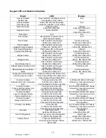
Alarm Inputs (J3) 

Input 

Description 

Maglock Alarm 

Input used to monitor the alarm relay on the maglock.  Will send 
alarm information to the nurse call system when activated. 

Stopper Alarm 

Input used to monitor the emergency exit button near the door.  Will 
send alarm information to the nurse call system when activated. 

Bond Sensor 

Input used to monitor the bond sensor on the maglock.  Will send 
alarm information to the nurse call system if the maglock is not 
securely locked when the door is supposed to be secure. 


User Types 

User 

Notes 

Master User 

Can enter programming mode, granted access through the door, and can reset 
alarms. 

Access User 

Granted access through the door only. 

Toggle User 

Disables the door security for a fixed amount of time.  See Keypad 
Configuration for changing the duration. 

Reset User 

Used to reset alarms only. 

REX User 

Tied to the REX input on J6 wiring harness.  Used to grant access only by 
default.  Can be changed in Keypad Configuration to also be allowed to reset 
alarms. 


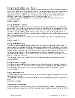
Master and Slave Keypads 

The AIO Keypad supports two keypads, one on each side of the door connected together via 
J5.  Power is shared between keypads through this connection as well so only one side 
needs to be powered.  LEDs and alarms should be replicated on both keypads so the two 
keypads should function as one. 
 
One keypad must be set as a master and one must be set as a slave.  If only one keypad is 
being used, it must be set as master.   
 
SW3 is used to configure the keypad’s mode. The keypad must be unpowered while changing 
the master/slave setting.  To set a keypad as master, SW3 must be in the down position.  To 
set a keypad as slave, SW3 must be in the up position.  
 
The slave keypad will automatically download all configuration from the master, so no 
programming is required on the slave. 
 
If you are converting a master into a slave, the reset button (SW2) on the back of the keypad 
must be pressed to clear the configuration on the keypad. 
 
If you are using any of the external inputs (J3 and J6), they must be connected to the master 
keypad. 
 
Programming can be performed on either keypad and both keypads will be updated. 

Summary of Contents for PalCare PAL-106050

Page 1: ...acility and doorways between secure and unsecure zones like a memory care wing If the door is opened without a valid code entered into the keypad it will audibly sound an alarm tone and send a message to the nurse call system alerting staff If a staff member wants to go through the door without sending an alert they can enter a valid code in the keypad allowing them to pass through the doorway wit...

Page 2: ... batteries If operating the keypad from batteries please ensure both batteries are installed When operating from batteries the device will turn off the backlighting LEDs and the relay will not activate to conserve battery power These features will function properly when running the keypad from an external power supply The use of electronic locks with the keypad is not supported on battery power Wh...

Page 3: ...low battery but will send an alarm for critical low battery The PAL 106060 Keypad comes with an Inovonics EN1941XS radio This radio has a custom message payload that allows detailed alarm support which will identify which alarm is active in the keypad In addition it will send out low battery and critical low battery signals The PAL 106070 Keypad does not come with a transmitter and is used as a sl...

Page 4: ...secure In battery operated mode the LED will be off to save power The keypad allows codes between 4 and 6 digits long The keypad can be configured to automatically accept a matching code without any additional button presses or can be configured to require a star after entering a valid code If an incorrect digit is entered the pound symbol button can be pressed to cancel the entered digits and sta...

Page 5: ...if configured to reset alarms Maintenance Cleaning should be performed by hand using a damp cloth and mild soap or disinfectant wipes designed for household use Ensure the keypad is fully dry prior to operating the unit Any moisture dirt or debris can cause erroneous button activations on the keypad Do Not Use the following products to clean the keypad Strong cleaning agents such as ammonia bleach...

Page 6: ...rizontal mark on the wall one inch lower than the top of the intended height 3 Install a single gang drywall box at this mark matching the top of the mark with the top of the drywall box cutout 4 Feed the needed wires into the drywall box and connect them to the proper pigtails Cap unused wires See wiring diagrams and pigtail pinouts for further details 5 Push the pigtail connectors through the wi...

Page 7: ...7 Document 106050 2019 PalatiumCare Inc Rev 1 3 3 Wiring Examples All wiring splices should be made in approved junction boxes Ensure all unused wires are capped off with wire nuts ...

Page 8: ...8 Document 106050 2019 PalatiumCare Inc Rev 1 3 3 Typical Wiring Door Scenarios ...

Page 9: ...9 Document 106050 2019 PalatiumCare Inc Rev 1 3 3 AIO Keypad Master and Slave Keypad Connections Delayed Egress Controller Example ...

Page 10: ...10 Document 106050 2019 PalatiumCare Inc Rev 1 3 3 AIO Keypad Wet Relay with PalCare Delayed Egress Maglock Example ...

Page 11: ...ction like a standard relay When the relay is in wet mode the common wire blue becomes a ground or negative wire The normally open wire green becomes positive when the relay is activated The normally closed wire gray becomes positive when the relay is deactivated You can directly connect a strike or maglock to these wires Please note you must still follow all life safety codes when installing this...

Page 12: ...hanged in Keypad Configuration to also be allowed to reset alarms Master and Slave Keypads The AIO Keypad supports two keypads one on each side of the door connected together via J5 Power is shared between keypads through this connection as well so only one side needs to be powered LEDs and alarms should be replicated on both keypads so the two keypads should function as one One keypad must be set...

Page 13: ...L approved latching hardware Units Models are intended to be connected to UL Listed Equipment not intended for Burglar or Fire Alarm Initiating or Indicating Devices Ambient Conditions For Indoor Use Only Wiring methods shall be in accordance with the National Electrical Code ANSI NFPA 70 This device complies with part 15 of FCC rules Operation is subject to following two conditions 1 This device ...

Page 14: ... following sequence including the stars 3 New Code New Code Reset User Code The Reset User code is used to reset alarms only It will not grant access through the door or allow you to enter programming mode To change the rest user code enter the following sequence including the stars 4 New Code New Code Relay Activation Mode The relay reactivation mode configures when the keypad will deactivate the...

Page 15: ...n programming mode 11 VALUE 3 Door Contact Debounce Timeout The door contact debounce timeout is the amount of time in deciseconds tenths of a second that the keypad will wait before it recognizes the door changing state between open and closed This is used when you have a closer that closes the door too fast and the door immediately bounces open slightly Adjusting this value can prevent a forced ...

Page 16: ...e correct code when entered If this option is disabled you must push after you enter the code to the keypad This option is useful if you are using codes of different length or are trying to match the functionality of a different manufacturer s keypad in your facility A value of 0 will not require a after the code A value of 1 will require a to be entered after the code The default value is 0 To ch...

Page 17: ...o Monitoring The change radio monitoring feature allows you to configure the keypad to poll the radio to ensure the EN1941XS radio module is connected and responding to the keypad If the radio module is disconnected not responding or a different module is inserted the keypad will start beeping and flashing the Radio Communication Error pattern until the problem is resolved If you are using the EN1...

Page 18: ... a second 11 VALUE 5 Change Delayed Egress Timer 0 disabled 0 15 or 30 seconds 11 VALUE 6 Change Delayed Egress Nuisance Delay 3 seconds 0 to 3 seconds 11 VALUE 7 Change Auxiliary Input Debounce Times 15 deciseconds 1 to 99 1 to 99 tenths of a second 30 0 VALUE Change Alarm Volume 9 volume 0 to 9 0 mute 9 loudest 30 1 VALUE Change Key Press Volume 9 volume 0 to 9 0 mute 9 loudest 30 2 VALUE Change...

Page 19: ...nuously 700ms ON 300ms OFF Continuous beeps 700ms ON 300ms OFF Configuration Data Request including access codes Flash Red 250ms ON 250ms OFF Flash Yellow 250ms ON 250ms OFF Flash Green 250ms 250ms OFF N A Trouble Condition Radio Module Communication Error Flash green and red LED 1x 200ms ON 200ms OFF 5 second pause and then repeated 1x 200ms ON 200ms OFF beep followed by 5 second pause and then r...

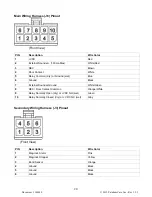
Page 20: ...lay Common dry or Ground wet Blue 6 Ground Black 7 External Sounder Ground White Green 8 REX Door Contact Common Orange White 9 Relay Normally Open dry or VDC NO wet Green 10 Relay Normally Closed dry or VDC NC wet Gray Secondary Wiring Harness J3 Pinout Front View PIN Description Wire Color 1 Mag lock Alarm Pink 2 Mag lock Stopper Yellow 3 Bond Sensor Orange 4 Ground Black 5 Ground Black 6 Ground...

Page 21: ...escription Wire Color 1 VDC from Battery White Red 2 VDC from Battery White Red 3 VDC from External Power Adapter Red 4 VDC from External Power Adapter Red 5 RS232 RX Green or Yellow 6 RS232 TX Yellow or Green 7 Ground Black 8 Ground Black Wiring needs pin 5 and pin 6 crossed for communication between keypads ...

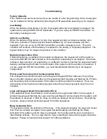
Page 22: ...shing the Radio Communication Error pattern until the problem is resolved If you are using the EN1941 transmitter you must disable Radio Monitoring in the keypad configuration Primary and Secondary Unit Communication Error If two keypads are interconnected via the Keypad to Keypad Wiring Harness J5 and they lose connection between each other both keypads will start beeping and flashing the Primary...

Page 23: ... causing a forced door alarm the closer may need to be adjusted to prevent this If you are unable to adjust the closer you can adjust the door contact debounce time in the configuration settings to prevent the alarm from occurring No Audible Alarm If no audible alarm is heard from the keypad during an alarm check your configuration settings for alarm volume If no audible alarm is heard after incre...

Reviews: