14
1-2017
Translation
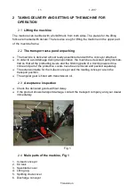
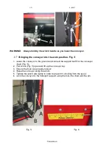
7. Splitting chute
8. Operating panel
9. Hydraulic connectors for log-table
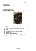
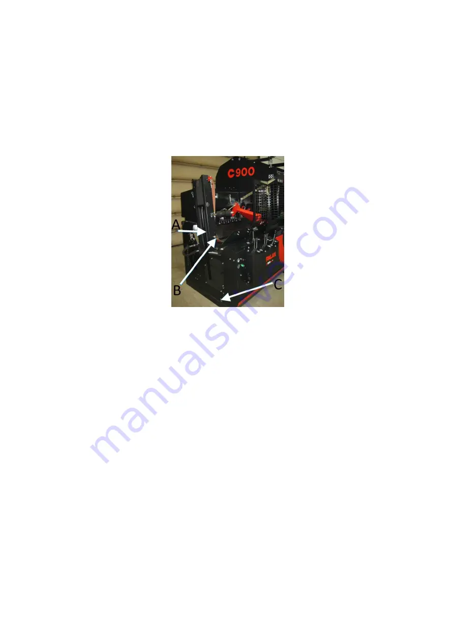
2.5 Bringing the table extension into the work position, Fig. 2
1. Disconnect the rubber strap A.
2. Pull open the locking lever B.
3. Swing the conveyor down and place the leg into the opening C in the frame. Re-con-
nect the rubber strap.
Fig. 2
2.6 Bringing the conveyor into the work position, Figs. 3 and 4
1. Remove the locking pins A for the conveyor, Fig. 3 and 4
2. Release the locks B.
3. Unwind the winch wire a few rounds.
4. Pull out the conveyor and leave it supported by the winch rope.
5. Lower the conveyor to the ground using the winch.
6. Pull open lock A, Fig. 5
7. Swing down the top of the conveyor.
8. Remove support bar B for the conveyor chain (Fig. 5) and place it in the holes at the
edge of the conveyor.
9. Put the splints back in place.
Summary of Contents for C900
Page 2: ...2 1 2017 Translation ...
Page 22: ...22 1 2017 Translation Fig 11A Fig 11B ...
Page 36: ...36 1 2017 Translation 12 ELECTRIC DIAGRAMS ...
Page 37: ...37 1 2017 Translation ...


