background image

85

ESP

AÑOL

en su caso hasta el apagado

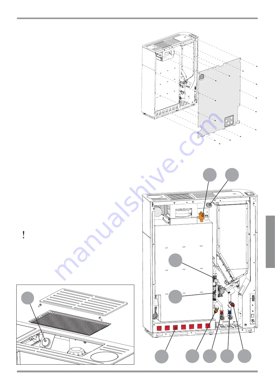
Para intervenir en las conexiones hidráulicas 
de forma sencilla se puede quitar por completo 

HO SDQHO SRVWHULRU ¿J SURFXUDQGR VLQ

embargo, que los tubos pasen a través de los 
correspondientes agujeros del panel posterior.

5.8.1 

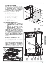
'HVFULSFLyQFLUFXLWRKLGUiXOLFR¿J

A) Manómetro

B)  Válvula automática de purga

C)  Grifo de carga

D)  Salida agua caliente al equipo (G3/4”F)

E)  Regreso agua del equipo (G3/4”F)

F)  Válvula de seguridad (G3/4”F)

G)  Recipiente de expansión cerrado

H) Circulador

I) Válvula 

anticondensación

5.8.2 

&RQH[LRQHVKLGUiXOLFDV¿J

‡

Conecte la estufa al equipo de calentamiento 
a través de los tubos de salida y de regreso 
(D-E).

‡

Prepare un tubo de descarga a perder, 
de diámetro adecuado, al que conectar la 
descarga de la válvula de seguridad (F).

Después de haber efectuado las conexiones 
hidráulicas es necesario cargar la caldera (grifo 
C) y la relativa purga (B) controlando la presión 
(1-1,2 bar en frío) mediante el manómetro (A).

En caso de que sea necesario, asegúrese de que 
la precarga del vaso expansión cerrado (G) es 
correcta.

MAXIMALER BETRIEBSDRUCK: 2,5 bar


Es conveniente lavar el equipo antes de ponerlo 
en funcionamiento.

$ ¿Q GH JDUDQWL]DU VLHPSUH XQD DOWD H¿FLHQFLD \

duración del producto se aconseja un equipo de 
ablandamiento para garantizar una dureza del 
agua inferior a 25-27 grados franceses y añadir 
en su caso al agua del equipo antialgas.

¿J

¿J

¿J

A

C

G

I

H

B

D

E

F

A

Summary of Contents for Ecofire Elisabeth Aria

Page 1: ...rchlesen Le présent manuel fait partie intégrante du produit Il est conseillé de lire attentivement les consignes avant l installation l entretien ou l utilisation du produit Este manual es parte integrante del producto Se recomienda leer detenidamente las instrucciones antes de la instalación el mantenimiento y el uso del producto IT GENERALITA AVVERTENZE INSTALLAZIONE MANUTENZIONE EN GENERAL INF...

Page 2: ...nous avez accordée en achetant notre produit et vous félicitions pour votre choix Q GH YRXV SHUPHWWUH GH SUR WHU DX PLHX GH YRWUH QRXYHDX SRrOH QRXV YRXV LQYLWRQV j suivre attentivement les instructions reportées dans cette notice Estimado Cliente Deseamos agradecerle por la preferencia que nos ha otorgado adquiriendo nuestro producto y lo felicitamos por su elección Para el mejor uso de su nueva ...

Page 3: ...NZE PER LA SICUREZZA 2 1 AVVERTENZE PER L INSTALLATORE 2 2 AVVERTENZE PER IL MANUTENTORE 2 3 AVVERTENZE PER L UTILIZZATORE 3 CARATTERISTICHE DEL COMBUSTIBILE 3 1 CARATTERISTICHE DEL COMBUSTIBILE 3 2 STOCCAGGIO DEI PELLET 4 MOVIMENTAZIONE E TRASPORTO 4 1 RIMOZIONE DALLA PALETTA DI TRASPORTO 5 INSTALLAZIONE 5 1 CONSIDERAZIONI GENERALI 5 2 PRECAUZIONI PER LA SICUREZZA 5 3 LUOGO DI INSTALLAZIONE DELLA...

Page 4: ...otto oggetto del presente manuale è costruito e collaudato seguendo le prescrizioni di sicurezza indicate nelle direttive europee di riferimento Questo manuale è indirizzato ai proprietari della stufa agli installatori utilizzatori e manutentori delle stufe ed è parte integrante del prodotto In caso di dubbi sul contenuto e per ogni chiarimento contattare il costruttore o il servizio di assistenza...

Page 5: ...ta o indiretta dovuta a LQVWDOOD LRQH QRQ FRQIRUPH DOOH QRUPDWLYH vigenti nel paese ed alle direttive di sicurezza LQRVVHUYDQ D SDU LDOH R WRWDOH GHOOH LVWUX LRQL contenute nel manuale LQVWDOOD LRQH GD SDUWH GL SHUVRQDOH QRQ TXDOL FDWR H QRQ DGGHVWUDWR XVR QRQ FRQIRUPH DOOH GLUHWWLYH GL VLFXUH D PRGL FKH H ULSDUD LRQL QRQ DXWRUL DWH GDO Costruttore effettuate sulla stufa XWLOL R GL ULFDPEL QRQ RUL...

Page 6: ...funzionante 7RJOLHUH O DOLPHQWD LRQH HOHWWULFD SULPD GL intervenire su parti elettriche elettroniche e connettori 2 3 AVVERTENZE PER L UTILIZZATORE Predisporre il luogo d installazione della stufa secondoiregolamentilocali nazionaleedeuropei D VWXID HVVHQGR XQ SURGRWWR GD ULVFDOGDPHQWR SUHVHQWD GHOOH VXSHU FL HVWHUQH SDUWLFRODUPHQWH calde Per questo motivo si raccomanda la massima cautela durante ...

Page 7: ...idità accettabili Il pellet umido e o freddo 5 C riduce la potenzialità termica del combustibile ed obbliga ad effettuare maggiore manutenzione di pulizia del braciere materiale incombusto e del focolare Porre particolare attenzione nello stoccaggio e movimentazione dei sacchi di pellet Deve essere evitata la sua frantumazione e la formazione di segatura Se viene immessa segatura nel serbatoio del...

Page 8: ...XQLVWLFL individuali e personali siano integri e perfettamente funzionanti C deve indossare i guanti antinfortunistici D deve indossare scarpe antinfortunistiche E deve usufruire di utensili muniti di isolamento elettrico F deve accertarsi che l area interessata alle fasi di montaggio e di smontaggio sia libera da ostacoli 5 3 LUOGO DI INSTALLAZIONE DELLA STUFA Nel libretto di prodotto allegato so...

Page 9: ...olarmente ventose ed esposte alle intemperie prevedere una protezione antipioggia ed antivento Accertarsi che la presa d aria sia posizionata in modo da non essere ostruita accidentalmente Nel caso fosse impossibile realizzare la presa d aria esterna nella parete posteriore alla stufa parete non perimetrale deve essere realizzato un foro in una parete esterna del locale dove viene posizionata la s...

Page 10: ... massimo di 3 variazioni di direzione oltre a quello derivante dal collegamento posteriore della stufa al camino utilizzando delle curve a 45 90 o dei raccordi a Tee J Utilizzare sempre un raccordo a Tee con tappo di ispezione ad ogni variazione orizzontale e verticale del percorso di scarico fumi Se possibile sul primo Tee all uscita dello scarico fumi della stufa collegare un tubo per l evacuazi...

Page 11: ... Lo scarico dei fumi attraverso un camino tradizionale Fig 5 8 può essere fatto purché ci si assicuri sullo stato di manutenzione del camino In caso di camino di sezione maggiore è necessario intubare il camino con una tubazione in acciaio con diametro in funzione del percorso opportunamente isolato Fig 5 9 Assicurarsi che il collegamento al camino in muratura sia opportunamente sigillato In caso ...

Page 12: ...imento allo schema elettrico presente tra le caratteristiche tecniche 5 7 3 ROOHJDPHQWR DOO XVFLWD IXPL J È possibile collegare la stufa al sistema fumario posteriormente oppure superiormente VHPSOLFHPHQWH UXRWDQGR OD FXUYD GL XVFLWD J 5 12 A Nel caso di uscita fumi verso l alto sarà necessario togliere il tappo superiore svitando le tre viti di VVDJJLR 5 8 IMPIANTO IDRAULICO Il collegamento all i...

Page 13: ...a e di ritorno D E Predisporre un tubo di scarico a perdere di diametro opportuno a cui collegare lo scarico della valvola di sicurezza F Dopo aver effettuato i collegamenti idraulici è necessario procedere con il carico della caldaia UXELQHWWR H LO UHODWLYR V DWR PRQLWRUDQGR la pressione 1 1 2 bar a freddo attraverso il manometro A Se necessario assicurarsi che la precarica del vaso espansione ch...

Page 14: ...eventualità in cui la temperatura dell acqua continui a crescere nonostante la modulazione In questo caso la stufa si riaccenderà solo se la differenza di temperatura tra il valore impostato e quello reale è maggiore di 20 C FRQVLJOLDELOH SHUWDQWR LQ TXHVWD FRQ JXUD LRQH LPSRVWDUH OD WHPSHUDWXUD GHOO DFTXD VX XQ YDORUH DOWR HV CONFIGURAZIONE 2 PSRVWDUH WDOH FRQ JXUD LRQH SHU DFFHQGHUH H VSHJQHUH O...

Page 15: ...ssere riattivata accidentalmente Staccare la spina dalla presa a muro Operare sempre con attrezzature appropriate per la manutenzione Terminata la manutenzione o le operazioni di riparazione prima di rimettere la stufa in servizio reinstallare tutte le protezioni e riattivare tutti i dispositivi di sicurezza 6 1 1 Manutenzione del sistema fumario Da effettuarsi almeno una volta all anno oppure ogn...

Page 16: ...UUHWWR IXQ LRQDPHQWR GHOOD VWXID resettare eventuali avvisi o allarmi ACCESSO AL CIRCUITO IDRAULICO MODELLO ELISABETH 7RJOLHUH OH GXH YLWL GHO SDQQHOOR VLQLVWUR J DEEDVVDUOR H V ODUOR YHUVR O HVWHUQR 6YLWDUH OH GXH YLWL GHO ULYHVWLPHQWR IURQWDOH J VROOHYDUOR H V ODUOR LQFOLQDQGROR OHJJHUPHQWH MODELLO GINGER 7RJOLHUH OH WUH YLWL GHO SDQQHOOR VLQLVWUR J e V ODUOR YHUVR O HVWHUQR ACCESSO AL VENTILATO...

Page 17: ...U L SXUFKp VL ULFRUUD VHPSUH D GLWWH DXWRUL DWH al recupero ed all eliminazione dei materiali in questione INDICAZIONE attenersi sempre e comunque alle normative in vigore nel Paese dove si opera per lo smaltimento dei materiali ed eventualmente per la denuncia di smaltimento ATTENZIONE 7XWWH OH RSHUD LRQL GL VPRQWDJJLR SHU OD GHPROL LRQH GHYRQR DYYHQLUH D VWXID IHUPD H SULYDWD GHOO HQHUJLD HOHWWU...

Page 18: ...e Piezas incluidas en el kit estufa CONFIGURAZIONE CONFIGURATION KONFIGURATION CONFIGURATION CONFIGURACIÒN 1 CONFIGURAZIONE CONFIGURATION KONFIGURATION CONFIGURATION CONFIGURACIÒN EVERSPRING 1 8 1 8 Sonda temperatura ambiente Room probe Raumtemperatur Fuehler Sonde température ambiante Sonda temperatura ambiental Componenti compresi nella stufa Components included in the stove Komponenten enthalte...

Page 19: ...as incluidas en el kit estufa CONFIGURAZIONE CONFIGURATION KONFIGURATION CONFIGURATION CONFIGURACIÒN 3 1 8 Sonda puffer Heat Storage probe Puffer Fuehler Sonde à brancher dans le ballon tampon Sonda deposito inercial T 1 8 Componenti compresi nella stufa Components included in the stove Komponenten enthalten in den Ofen Composants prevus dans le poêle Piezas incluidas en el kit estufa CONFIGURAZIO...

Page 20: ......

Page 21: ...ERY OF THE STOVE 2 SAFETY WARNINGS 2 1 INSTALLATION WARNINGS 2 2 MAINTENANCE WARNINGS 2 3 WARNINGS FOR THE USER 3 FUEL SPECIFICATIONS 3 1 FUEL SPECIFICATIONS 3 2 STORING THE PELLETS 4 HANDLING AND TRANSPORT 4 1 REMOVING THE STOVE FROM THE PALLET 5 INSTALLATION 5 1 GENERAL INFORMATION 5 2 SAFETY PRECAUTIONS 5 3 STOVE INSTALLATION SITE 5 4 COMBUSTION AIR 5 5 FLUE GAS EXHAUST 5 6 LEVELLING THE STOVE ...

Page 22: ...TION The appliance is manufactured and tested to conform with the safety standards indicated in the applicable European directives This manual is intended for owners installers users and maintenance personnel of stoves and is an integral part of the product If there are any doubts regarding the contents of this manual or for any other explanations please contact the manufacturer or an authorised s...

Page 23: ... declines all liability both civil and criminal direct or indirect deriving from installation not in compliance with the standards in force in the country concerned and with safety directives partial or total failure to follow the instructions provided in this manual LQVWDOODWLRQ E XQTXDOL HG DQG XQWUDLQHG personnel use not in compliance with safety directives PRGL FDWLRQV DQG UHSDLUV RQ WKH VWRYH...

Page 24: ...power before working on electrical or electronic parts and connectors 2 3 WARNINGS FOR THE USER Prepare the stove installation site in accordance with local national and European regulations As the stove is a heating appliance it has very hot outside surfaces For this reason maximum FDUH PXVW EH SDLG GXULQJ RSHUDWLRQ VSHFL FDOO do not touch or get too close to the glass door to avoid getting burne...

Page 25: ...m as long as the temperature and humidity are acceptable Damp and or cold pellets 5 C reduce the fuel heat value and mean the burn pot unburned PDWHULDO DQG UHER ZLOO QHHG WR EH FOHDQHG PRUH frequently Pay special care when storing and handling the sacks of pellets Make sure these are not crushed to prevent the pellets from becoming sawdust Sawdust introduced into the hopper may block the pellet f...

Page 26: ... that personal protective equipment is in perfectly working order C always wear safety gloves D always wear safety shoes E always use electrically insulated tools F make sure that the area being used for assembly and dismantling is clear of any obstacles 5 3 STOVE INSTALLATION SITE The enclosed Product technical details show the minimum clearances from combustible materials and objects expressed i...

Page 27: ...especially windy areas or places exposed to bad weather install rain and wind protection elements Make sure that the air vent is located in such a way that it can t be accidentally obstructed If it s not possible to make a fresh air opening in the wall behind the stove not a perimeter wall an opening must be made on the wall in the room where the stove is installed that faces the outside If no fre...

Page 28: ...east three changes in direction DORQJ WKH ÀXH LQ DGGLWLRQ WR WKH ÀXH FRQQHFWLRQ at the rear of the stove using 45 or 90 angle connectors or T connectors Fig 5 7 Use always a T connector with inspection cap on DOO KRUL RQWDO RU YHUWLFDO FKDQJHV LQ ÀXH GLUHFWLRQ If it is possible connect a pipe at the bottom of the T junction in order to discharge the smoke condensate WKDW FRXOG IRUP LQ WKH ÀXH JDV ...

Page 29: ...ited by law and affect proper stove operation 7KH ÀXH JDV FDQ EH GLVFKDUJHG WKURXJK D WUDGLWLRQDO chimney Fig 5 8 as long as you make sure on the state of maintenance of the chimney For larger chimneys suitably insulated steel pipes need to be inserted on the inside diameter according to the length Fig 5 9 Makes sure connections to brick chimneys are suitably sealed I WKH ÀXHV UXQ WKURXJK ZRRGHQ U...

Page 30: ...KQLFDO VSHFL FDWLRQV 5 7 3 RQQHFWLQJ WR ÀXH JDV RXWOHW J RX FDQ FRQQHFW WKH VWRYH WR WKH ÀXH V VWHP DW the rear or the top simply by rotating the output EHQG J Q WKH FDVH RI WKH ÀXH RXWOHW DW WKH WRS RX ZLOO need to remove the top cap by removing the three LQJ VFUHZV 5 8 PLUMBING SYSTEM Connection to the plumbing system and the plumbing system must be in compliance with current national laws and s...

Page 31: ...e After making the water connections it is necessary to proceed with the boiler load tap C and the related vent B monitoring the pressure 1 1 2 bar cold through the pressure gauge A If necessary ensure that the closed expansion vessel G preload is correct MAXIMUM OPERATING PRESSURE 2 5 bar It is good practice to proceed with washing the system before commissioning the operational system 7R HQVXUH ...

Page 32: ...The stove will turn off also in case the water temperature continues to rise despite the modulation In this case the stove will turn on only if the temperature difference between the value you set up and the real one is higher than 20 C Q WKLV FRQ JXUDWLRQ LW LV WKHUHIRUH UHFRPPHQGHG WR UHJXODWH D KLJK ZDWHU WHPSHUDWXUH H CONFIGURATION 2 6HW WKLV FRQ JXUDWLRQ WR VZLWFK WKH VWRYH RQ RU RII PDQXDOO ...

Page 33: ...HG LQ LUHFWLYH Make sure the mains power is off at the master power switch Ensure that the power supply cannot be restored accidentally Remove the power plug from the socket Always use proper tools Once maintenance or repair activities are completed reinstall all the protections and reactivate all the safety devices prior to restarting the system 6 1 1 6HUYLFLQJ WKH ÀXH V VWHP This must be done at...

Page 34: ...ting properly reset any warnings and alarms ACCESS TO THE WATER CIRCUIT MODEL ELISABETH 5HPRYH WKH WZR VFUHZV RQ WKH OHIW SDQHO J A lower it and pull it outwards 8QVFUHZ WKH WZR VFUHZV RQ WKH IURQW FDVLQJ J 6 1 B lift it up and remove it tilting it slightly MODEL GINGER 5HPRYH WKH WKUHH VFUHZV RQ WKH OHIW SDQHO J 6 2 and pull it outwards ACCESS TO SMOKE EXTRACTION FAN In case of maintenance you ca...

Page 35: ...osed of by companies authorised to recover and dispose of the materials in question INSTRUCTION always observe the standards in force in the country where the stove is decommissioned as regards disposal of the materials and the waste disposal report where required IMPORTANT All dismantling operations for decommissioning the stove must be performed when the stove is off and disconnected from the po...

Page 36: ... Piezas incluidas en el kit estufa CONFIGURAZIONE CONFIGURATION KONFIGURATION CONFIGURATION CONFIGURACIÒN 1 CONFIGURAZIONE CONFIGURATION KONFIGURATION CONFIGURATION CONFIGURACIÒN EVERSPRING 1 8 1 8 Sonda temperatura ambiente Room probe Raumtemperatur Fuehler Sonde température ambiante Sonda temperatura ambiental Componenti compresi nella stufa Components included in the stove Komponenten enthalten...

Page 37: ...as incluidas en el kit estufa CONFIGURAZIONE CONFIGURATION KONFIGURATION CONFIGURATION CONFIGURACIÒN 3 1 8 Sonda puffer Heat Storage probe Puffer Fuehler Sonde à brancher dans le ballon tampon Sonda deposito inercial T 1 8 Componenti compresi nella stufa Components included in the stove Komponenten enthalten in den Ofen Composants prevus dans le poêle Piezas incluidas en el kit estufa CONFIGURAZIO...

Page 38: ......

Page 39: ...ERUNG DES OFENS 2 SICHERHEITSHINWEISE 2 1 HINWEISE FÜR DEN INSTALLATIONSTECHNIKER 2 2 HINWEISE FÜR DEN WARTUNGSTECHNIKER 2 3 HINWEISE FÜR DEN BENUTZER 3 BRENNSTOFF EIGENSCHAFTEN 3 1 BRENNSTOFFEIGENSCHAFTEN 3 2 LAGERUNG DER PELLETS 4 HANDLING UND TRANSPORT 4 1 ABLADEN VON DER TRANSPORTPALETTE 5 INSTALLATION 5 1 ALLGEMEINES 5 2 SICHERHEITSMASSNAHMEN 5 3 AUFSTELLUNGSORT DES OFENS 5 4 VERBRENNUNGSLUFT...

Page 40: ...eserAnleitungbetroffeneProduktwirdgemäß den Sicherheitsvorschriften der EU Bezugsrichtlinien gebaut und geprüft Dieses Handbuch ist wesentlicher Bestandteil des Produkts und für die Eigentümer des Ofens sowie für die Installationstechniker Betreiber und WartungstechnikervonÖfenbestimmt ImZweifelsfall und für eventuelle Rückfragen wenden Sie sich bitte an den Hersteller oder an den Vertragskundendi...

Page 41: ...eschlossen Installation in Abweichung von den im Installationsland geltenden Bestimmungen und von den Sicherheitsvorschriften Teilweise oder gänzliche Missachtung der in diesem Handbuch enthaltenen Anleitungen QVWDOODWLRQ GXUFK QLFKW TXDOL LHUWHV XQG QLFKW geschultes Personal von den Sicherheitsrichtlinien abweichender Gebrauch nicht vom Hersteller genehmigte am Ofen vorgenommene Umbauten und Repa...

Page 42: ...cht funktionstüchtig Vor Eingriffen an elektrischen elektronischen Teilen oder Steckverbindern die Spannungszufuhr unterbrechen 2 3 HINWEISE FÜR DEN BENUTZER HUHLWHQ 6LH GHQ XIVWHOOXQJVRUW GHV 2IHQV JHPl den lokalen nationalen und europäischen Bestim mungen vor Da der Ofen als Heizgerät dient werden seine Au HQÀlFKHQ EHVRQGHUV KHL HVKDOE LVW ZlKUHQG des Betriebs maximale Vorsicht geboten insbe son...

Page 43: ...es Ofens oder in einem benachbarten Raum zu lagern damit sie eine akzeptable Temperatur und Feuchtigkeit haben Feuchte und oder kalte 5 C Pellets reduzieren die Wärmeleistung des Brennstoffs und zwingen zu einer KlX JHUHQ 5HLQLJXQJVZDUWXQJ GHU UHQQVFKDOH unverbranntes Material und des Feuerraums Bei Lagerung und Handhabung der Pelletssäcke vorsichtig vorgehen Dabei ist zu vermeiden dass die Pellet...

Page 44: ...ersönlichen Schutzausrüstungen vollständig und funktionstüchtig sind C muss er Schutzhandschuhe tragen D muss er Sicherheitsschuhe tragen E muss er elektrisch isoliertes Werkzeug benutzen F muss er sicherstellen dass der Bereich in dem die Montage und Demontagearbeiten ausgeführt werden frei von Hindernissen ist 5 3 AUFSTELLUNGSORT DES OFENS Im beigelegten Produkthandbuch sind die beim Aufstellen ...

Page 45: ...ausgesetzten Stellen ist ein Regen und Windschutz vorzusehen Sicherstellen dass der Lufteinlass so positioniert ist dass er nicht versehentlich verstopfen kann Falls an der Wand hinter dem Ofen kein Außenlufteinlass angebracht werden kann keine Außenwand muss die Öffnung an einer anderen Außenwand des Aufstellungsraumes angebracht werden Sollte es nicht möglich sein im Raum einen Außenlufteinlass ...

Page 46: ...Richtung nicht mehr als 3 Mal gewechselt werden dazu 45 90 Rohrkrümmer oder T Stücke verwenden Abb 5 7 Bei jeder waagerechten und senkrechten Richtungsänderung der Abgasführung immer ein T Stück mit Inspektionsklappe verwenden Wenn es möglich ist ein Rohr unten im ersten T Stück der Abgasführung verbinden um den Rauchabzug des Kondenswassers das sich in dem Schornstein bilden kann zu ermöglichen A...

Page 47: ...eien Betrieb des Ofens Es ist möglich den Rauchabzug in einem traditionellen Kamin Abb 5 8 einzubauen sofern dieser in gutem Zustand ist Wenn der Schornstein einen größeren Querschnitt hat muss er mit einem angemessen isolierten Stahlrohr verrohrt werden Durchmesser je nach Leitungsverlauf Abb 5 9 Sicherstellen dass der Anschluss am gemauerten Schornstein gut abgedichtet ist Wenn Rohre durch Holzd...

Page 48: ...ie Verbindung zwischen diesen Schaltplan 6SH L NDWLRQHQ X VHKHQ 5 7 3 Verbindung zum Rauchablass Abb 5 12 Der Ofen kann hinten oder oben an den Rauchablass angeschlossen wird indem einfach der Winkel des Ablasses gedreht wird Abb 5 12 A Bei einem nach oben gerichteten Rauchgasablass muss die obereAbdeckung entfernt werden indem die drei Befestigungsschrauben gelöst werden 5 8 HYDRAULIKANLAGE Der A...

Page 49: ...ge anschließen EinÜberlaufablassleitungmitentsprechendem Durchmesser bereitstellen an die der Ablass des Sicherheitsventils F anschlossen wird Nachdem die Wasseranschlüsse vorgenommen wurden muss der Kessel Hahn C gefüllt und entsprechenden entlüftet B werden wobei der Druck 1 1 2 bar kalt auf dem Manometer Abb 5 15 A überwacht wird Wenn notwendig sicherstellen das die Vorlast des Ausdehnungsgefäß...

Page 50: ...n Q GLHVHU RQ JXUDWLRQ ZLUG GHU 2IHQ DXVJHVFKDOWHW VREDOG GLH lUPHDQIRUGHUXQJ GHV 5DXPWKHUPRVWDWV erfüllt ist oder er moduliert bei Erreichen der eingestellten Wassertemperatur die Leistung um den Verbrauch niedrig zu halten Der Ofen wird während des Modulation Betrieb falls die Wasser Temperatur 10 C über den eingestellten Sollwert steigen sollte automatisch aus gehen und wieder einschalten erst ...

Page 51: ...tzausrüstung benutzen Sicherstellen dass der Hauptschalter der Linie ausgeschaltet ist Sicherstellen dass die Stromversorgung nicht versehentlich wieder eingeschaltet werden kann Den Netzstecker aus der Steckdose ziehen ImmermitdenfürdenjeweiligenWartungseingriff geeigneten Werkzeugen arbeiten Nach den Wartungs bzw Reparaturarbeiten alle Schutzabdeckungen installierten und alle Sicherheitseinricht...

Page 52: ... Reset etwaiger Meldungen oder Alarme ZUGRIFF AUF DEN WASSERKREISLAUF MODELL ELISABETH Die beiden Schrauben der linken Wand Abb 6 1 A entfernen diese absenken und nach außen herausziehen Die beiden Schrauben der Verkleidung vorn Abb 6 1 B entfernen diese heben und herausziehen indem sie leicht geneigt wird MODELL GINGER Die beiden Schrauben der linken Wand Abb 6 2 entfernen und nach außen herauszi...

Page 53: ...ehmen beauftragt die zur Sammlung und Beseitigung des fraglichen Materials autorisiert sind HINWEIS Halten Sie sich bei der Entsorgung der Materialien und gegebenenfalls in Bezug auf die Entsorgungsmeldung immer strikt an die im betreffenden Land geltenden Vorschriften ACHTUNG Alle Arbeiten für Demontage und Verschrottung dürfen erst durchgeführt werden wenn der Ofen ausgeschaltet ist und die Span...

Page 54: ...e Piezas incluidas en el kit estufa CONFIGURAZIONE CONFIGURATION KONFIGURATION CONFIGURATION CONFIGURACIÒN 1 CONFIGURAZIONE CONFIGURATION KONFIGURATION CONFIGURATION CONFIGURACIÒN EVERSPRING 1 8 1 8 Sonda temperatura ambiente Room probe Raumtemperatur Fuehler Sonde température ambiante Sonda temperatura ambiental Componenti compresi nella stufa Components included in the stove Komponenten enthalte...

Page 55: ...as incluidas en el kit estufa CONFIGURAZIONE CONFIGURATION KONFIGURATION CONFIGURATION CONFIGURACIÒN 3 1 8 Sonda puffer Heat Storage probe Puffer Fuehler Sonde à brancher dans le ballon tampon Sonda deposito inercial T 1 8 Componenti compresi nella stufa Components included in the stove Komponenten enthalten in den Ofen Composants prevus dans le poêle Piezas incluidas en el kit estufa CONFIGURAZIO...

Page 56: ......

Page 57: ...RITÉ 2 1 RECOMMANDATIONS POUR L INSTALLATEUR 2 2 RECOMMANDATIONS POUR LE RESPONSABLE DE L ENTRETIEN 2 3 CONSIGNES DESTINEES A L UTILISATEUR 3 CARACTERISTIQUES DU COMBUSTIBLE 3 1 CARACTERISTIQUES DU COMBUSTIBLE 3 2 STOCKAGE DU PELLET 4 MANUTENTION ET TRANSPORT 4 1 RETRAIT DU POELE DE LA PALETTE DE TRANSPORT 5 INSTALLATION 5 1 CONSIDERATIONS GENERALES 5 2 MESURES POUR LA SECURITE 5 3 LIEU D INSTALLA...

Page 58: ...V GH VpFXULWp pHV SDU XQH OpJLVODWLRQ VSpFL TXH en vigueur dans l État où le poêle est installé 1 PRÉAMBULE Le produit visé par le présent manuel a été construit et assemblé suivant les prescriptions de sécurité indiquées dans les directives européennes de référence Ce manuel est destiné à l usage des utilisateurs des installateurs poseurs et manutentionnaires des poêles En cas de doute sur le con...

Page 59: ...lation non conforme aux normes et à la réglementation en vigueur dans l Etat ou le poêle est installé Manque d entretien de la part de l utilisateur ou de l installateur 1RQ UHVSHFW GHV LQVWUXFWLRQV JXUDQW GDQV OH présent manuel Installation faite par des personnes mal ou non formées Utilisation non conforme aux consignes de sécurité 0RGL FDWLRQV RX UpSDUDWLRQV HIIHFWXpHV VDQV l autorisation du fa...

Page 60: ...TILISATEUR 3UpYRLU XQ OLHX G LQVWDOODWLRQ GX SRrOH FRQIRUPH j OD législation locale nationale et européenne S agissant d un appareil de chauffage les surfaces externes du poêle sont particulièrement chaudes La prudence maximale est recommandée pendant son fonctionnement notamment ne pas toucher et ne pas s approcher de la vitre de la porte au risque de se brûler ne pas toucher au raccordement des ...

Page 61: ... ou se trouve le poêle RX GDQV XQH SLqFH DGMDFHQWH D Q G DYRLU XQH température et un taux d humidité acceptables HV JUDQXOpV KXPLGHV HW RX IURLGV UpGXLVHQW la puissance thermique du pellet et l on doit procéder à plus de fréquence de nettoyage du brasero imbrûlés Portez une attention particulière à l entreposage et j OD PDQXWHQWLRQ GHV VDFV GH JUDQXOpV D Q G pYLWHU le concassage et la formation de...

Page 62: ...server les mesures de sécurité prévues par la loi notamment A QH SDV RSpUHU GDQV GHV FRQGLWLRQV GLI FLOHV B travailler en parfaites conditions psycho SK VLTXHV HW YpUL HU O pWDW GH O pTXLSHPHQW GH protection individuelle C porter des gants de protection D porter des chaussures de protection E utiliser des outils munis d une isolation électrique F YpUL HU VL OD RQH GH WUDYDLO HVW GpJDJpH HW sans ob...

Page 63: ...ouvez également prendre l air directement dans le vide sanitaire s il est ventilé La section des grilles du vide sanitaire doit correspondre à 5 fois la surface des grilles en cm de la surface en m du rez de chaussée Exemple Rez de chaussée de 100 m donne 500 cm de surface de grille Fig 5 4 G grille Il ne peut pas être considéré comme une entrée d air si l habitation est équipée d une Ventilation ...

Page 64: ...nconduitisolélorsquecelui ci est situé à l extérieur de l habitation et sa hauteur doit dépasser le faîtage de 40 cm conformément à l arrêté de 1969 Ce conduit ne doit rien avoir autour dans un rayon de 8 mètres Zone 1 Le raccordement du poêle doit être le plus court possible et ne doit pas dépasser 2 coudes à 90 1 coude à 90 2 coudes à 45 Le Tè à la sortie de l appareil n est pas compté Si possib...

Page 65: ...aire Chaque installateur devra fournir en conformité avec les 78 OD FKH GH FDOFXO VXLYDQW OD QRUPH 1 Pour améliorer l isolation du conduit il est conseillé d isoler au maximum celui ci pour éviter la condensation et le point de rosée Les températures de sortie des fumées d un poêle à granulés sont inférieures à celle des poêles à bûches Pour l isolation utilisez uniquement des produits autorisés p...

Page 66: ...age GDQV OHV VSpFL FDWLRQV 5 7 3 5DFFRUGHPHQW j OD VRUWLH GHV IXPpHV J Le poêle peut être raccordé au système de fumées postérieurement ou supérieurement en WRXUQDQW OH FRXGH GH VRUWLH J En cas de sortie des fumées vers le haut il faudra enlever le bouchon supérieur en dévissant les WURLV YLV GH DWLRQ 5 8 INSTALLATION HYDRAULIQUE Le raccordement entre l installation et le système hydraulique doit ...

Page 67: ...réparer un tuyau d évacuation perdu de diamètre conforme auquel brancher l évacuation de la soupape de sûreté F Après avoir effectué les raccordements hydrauliques procéder au remplissage de la chaudière robinet C et l évent respectif B en contrôlant la pression 1 1 2 bars à froid à travers le manomètre A S assurer si nécessaire que la précharge du vase d expansion fermé G soit correcte MAXIMALER ...

Page 68: ...H GH O HDX sera atteinte Le poêle s éteindra aussi dans l éventualité où la température de l eau continue à augmenter malgré la modulation En ce cas le poêle s allumera seulement si la différence de température entre la valeur sélectionnée et celle réelle est majeure de 20 C O HVW SRXUWDQW FRQVHLOOp GDQV FHWWH FRQ JXUDWLRQ GH UpJOHU XQH KDXWH WHPSpUDWXUH GH O HDX H CONFIGURATION 2 0HWWUH DX SRLQW ...

Page 69: ...V SDU OD GLUHFWLYH CEE Désactiver le disjoncteur principal 9pUL HU TXH O DOLPHQWDWLRQ QH SHXW SDV rWUH UpWDEOLH DFFLGHQWHOOHPHQW pEUDQFKHU OD FKH de la prise murale Toujours travailler avec des outils appropriés aux opérations d entretien A la fin des opérations d entretien ou de réparation et avant de remettre le système en service remonter toutes les protections et réactiver tous les dispositifs...

Page 70: ...rOH réinitialiser les avis ou alarmes ACCÈS AU CIRCUIT HYDRAULIQUE MODÈLE ELISABETH QOHYHU OHV GHX YLV GX SDQQHDX JDXFKH J A le baisser et le tirer vers l extérieur pYLVVHU OHV GHX YLV GX UHYrWHPHQW IURQWDO J B le soulever et le tirer en l inclinant légèrement MODÈLE GINGER QOHYHU OHV WURLV YLV GX SDQQHDX JDXFKH J HW le tirer vers l extérieur ACCÈS AU VENTILATEUR DES FUMÉES En cas d entretien on p...

Page 71: ...WUH FRQ pV j GHV WLHUV j FRQGLWLRQ TX LO V DJLVVH G HQWLWpV autorisées au ramassage et au traitement des déchets en question INDICATION respecter toujours la législation en vigueur dans le pays où s opère le traitement des déchets et éventuellement pour la déclaration de mise au rebut ATTENTION Toutes les opérations de désossement doivent s effectuer avec le poêle éteint et débranché du secteur en...

Page 72: ...e Piezas incluidas en el kit estufa CONFIGURAZIONE CONFIGURATION KONFIGURATION CONFIGURATION CONFIGURACIÒN 1 CONFIGURAZIONE CONFIGURATION KONFIGURATION CONFIGURATION CONFIGURACIÒN EVERSPRING 1 8 1 8 Sonda temperatura ambiente Room probe Raumtemperatur Fuehler Sonde température ambiante Sonda temperatura ambiental Componenti compresi nella stufa Components included in the stove Komponenten enthalte...

Page 73: ...as incluidas en el kit estufa CONFIGURAZIONE CONFIGURATION KONFIGURATION CONFIGURATION CONFIGURACIÒN 3 1 8 Sonda puffer Heat Storage probe Puffer Fuehler Sonde à brancher dans le ballon tampon Sonda deposito inercial T 1 8 Componenti compresi nella stufa Components included in the stove Komponenten enthalten in den Ofen Composants prevus dans le poêle Piezas incluidas en el kit estufa CONFIGURAZIO...

Page 74: ......

Page 75: ...VERTENCIAS PARA EL INSTALADOR 2 2 ADVERTENCIAS PARA EL ENCARGADO DEL MANTENIMIENTO 2 3 ADVERTENCIAS PARA EL USUARIO 3 CARACTERÍSTICAS DEL COMBUSTIBLE 3 1 CARACTERÍSTICAS DEL COMBUSTIBLE 3 2 ALMACENAMIENTO DE LOS PELLETS 4 DESPLAZAMIENTO Y TRANSPORTE 4 1 EXTRACCIÓN DE LA PALETA DE TRANSPORTE 5 INSTALACIÓN 5 1 CONSIDERACIONES GENERALES 5 2 PRECAUCIONES SOBRE LA SEGURIDAD 5 3 LUGAR DE INSTALACIÓN DE ...

Page 76: ...ERAL El producto que es objeto del presente manual está fabricado y probado según las prescripciones de seguridad de las directivas europeas de referencia Este manual está dirigido a los propietarios de la estufa a los instaladores los usuarios y los encargados del mantenimiento de las estufas y es parte del producto En caso de dudas sobre el contenido y para cualquier aclaración contactar con el ...

Page 77: ... o penal directa o indirecta debida a Instalación no conforme con las normativas vigentes en el país y con las directivas de seguridad Incumplimientoparcialototaldelasinstrucciones contenidas en el manual QVWDODFLyQ SRU SDUWH GH SHUVRQDO QR FXDOL FDGR y no capacitado Uso no conforme con las directivas de seguridad 0RGL FDFLRQHV UHSDUDFLRQHV UHDOL DGDV HQ OD estufa y no autorizadas por el fabricant...

Page 78: ...e seguridad no está calibrado o no funciona la estufa debe considerarse que no funciona Desconectar la alimentación eléctrica antes de intervenir en las partes eléctricas electrónicas y conectores 2 3 ADVERTENCIAS PARA EL USUARIO Preparar el lugar de instalación de la estufa según los reglamentos locales nacionales y europeos La estufa siendo un producto de calefacción SUHVHQWD VXSHU FLHV H WHUQDV...

Page 79: ... en el local contiguo siempre que la temperatura y la humedad sean las adecuadas Los pellets húmedos y o fríos 5 C reducen la potencialidad térmica del combustible y obligan a realizar un mantenimiento de limpieza mayor de los braseros material no quemado y del hogar Poner cuidado en el almacenamiento y desplazamiento de las bolsas de pellets Debe evitarse su rotura y la formación de aserrín Si se...

Page 80: ...n perfectas condiciones de funcionamiento C Debe llevar los guantes de protección D Debe llevar calzado de protección E Debe usar herramientas con aislamiento eléctrico F Debe asegurarse que el área destinada a las fases de montaje y desmontaje estén libres de obstáculos 5 3 LUGAR DE INSTALACIÓN DE LA ESTUFA En la documentacion de los Datos Técnicos del Producto adjunto se indican las distancias m...

Page 81: ...e preparar una protección contra la lluvia y el viento Asegurarse que la toma de aire esté colocada de modo que no sea obstruida de forma accidental En el caso que fuese imposible realizar la toma de aire externa en la pared posterior de la estufa pared no perimetral debe realizarse un agujero en una pared externa del local donde se posiciona la estufa Si no fuese posible realizar la toma de aire ...

Page 82: ...ciones de dirección además del aquel que deriva de la conexión posterior de la estufa a la chimenea utilizando codos de 45 90 o acoples en T Utilizar siempre un acople en T con tapón de inspección en cada cambio horizontal y vertical del recorrido del escape de humos Si es posible conectar un tubo abajo del primer T al nivel de la salida de humos de la estufa para permitir la evacuación del agua d...

Page 83: ...cionamiento de la estufa La salida de humos por la chimenea tradicional Fig 5 8 se puede realizar siempre y cuando se asegure el estado de mantenimiento de la chimenea Si la chimenea es de mayor sección es necesario intubarla con un tubo de acero con un diámetro que depende del recorrido que esté debidamente aislado Fig 5 9 Asegurarse que la conexión de la chimenea a la mampostería esté debidament...

Page 84: ...ura programada Para la conexión consulte el diagrama de FDEOHDGR HQ ODV HVSHFL FDFLRQHV 5 7 3 RQH LyQ D OD VDOLGD GH KXPRV J Es posible conectar la estufa al sistema de humos posterior o superiormente girando simplemente OD FXUYD GH VDOLGD J En caso de salida de humos hacia arriba será necesario quitar el tapón superior desenroscando ORV WUHV WRUQLOORV GH MDFLyQ 5 8 EQUIPO HIDRÁULICO La conexión a...

Page 85: ...ntamiento a través de los tubos de salida y de regreso D E Prepare un tubo de descarga a perder de diámetro adecuado al que conectar la descarga de la válvula de seguridad F Después de haber efectuado las conexiones hidráulicas es necesario cargar la caldera grifo C y la relativa purga B controlando la presión 1 1 2 bar en frío mediante el manómetro A En caso de que sea necesario asegúrese de que ...

Page 86: ... OD HVWXID VH DSDJD FXDQGR HO WHUPRVWDWR H WHUQR DOFDQ D OD WHPSHUDWXUD MDGD R ELHQ modulará la potencia para mantener al mínimo los consumos cuando alcance la temperatura programada para el agua La estufa se apagará también en la eventualidad de que la temperatura del agua sigue aumentando a pesar de la modulación En este caso la estufa se encenderá solo si la diferencia de temperatura entre el v...

Page 87: ...do por completo Utilizar los dispositivos de protección individual previstos por la directiva 89 391 CEE Asegurarse de que el interruptor general de línea esté apagado Asegurarse de que la alimentación no pueda reactivarse de forma accidental Quitar la clavija de la toma de la pared Utilizar siempre los equipos adecuados para el mantenimiento O QDOL DU HO PDQWHQLPLHQWR R ODV RSHUDFLRQHV de reparac...

Page 88: ...ar los residuos de pellet del depósito YHUL FDU HO FRUUHFWR IXQFLRQDPLHQWR GH OD HVWXID restablecer eventuales avisos o alarmas ACCESO AL CIRCUITO HIDRÁULICO MODELO ELISABETH 4XLWH ORV GRV WRUQLOORV GHO SDQHO L TXLHUGR J A bájelo y sáquelo Desenrosque los dos tornillos del revestimiento IURQWDO J OHYiQWHOR ViTXHOR LQFOLQiQGROR ligeramente MODELO GINGER 4XLWH ORV WUHV WRUQLOORV GHO SDQHO L TXLHUGR ...

Page 89: ...mpre que se recurra a empresas autorizadas para la recuperación y la eliminación de los materiales en cuestión INDICACIÓN Cumplir siempre con las normativas en vigor en el país donde se realiza la eliminación de los materiales y eventualmente para denunciar el mismo ATENCIÓN Todas las operaciones de desmontaje para la demolición deben realizarse con la estufa parada y sin conexión a fuente de ener...

Page 90: ...le Piezas incluidas en el kit estufa CONFIGURAZIONE CONFIGURATION KONFIGURATION CONFIGURATION CONFIGURACIÒN 1 CONFIGURAZIONE CONFIGURATION KONFIGURATION CONFIGURATION CONFIGURACIÒN EVERSPRING 1 8 1 8 Sonda temperatura ambiente Room probe Raumtemperatur Fuehler Sonde température ambiante Sonda temperatura ambiental Componenti compresi nella stufa Components included in the stove Komponenten enthalt...

Page 91: ...as incluidas en el kit estufa CONFIGURAZIONE CONFIGURATION KONFIGURATION CONFIGURATION CONFIGURACIÒN 3 1 8 Sonda puffer Heat Storage probe Puffer Fuehler Sonde à brancher dans le ballon tampon Sonda deposito inercial T 1 8 Componenti compresi nella stufa Components included in the stove Komponenten enthalten in den Ofen Composants prevus dans le poêle Piezas incluidas en el kit estufa CONFIGURAZIO...

Page 92: ...prodotti Palazzetti accepts no liability for any mistakes in this handbook and is free to modify the features of its products without prior notice Die Firma Palazzetti übernimmt für eventuelle Fehler in diesem Heft keine Verantwortung und behält sich das Recht vor die Eigenschaften ihrer Produkte ohne Vorbescheid zu ändern Palazzetti décline toute responsabilité en cas d erreurs dans la présente d...

Reviews: