42/144
INSTALLATION MANUAL
- cod. 00 477 0811 - 12/2011 - Palazzetti - PN - Italy
INSTALLATION
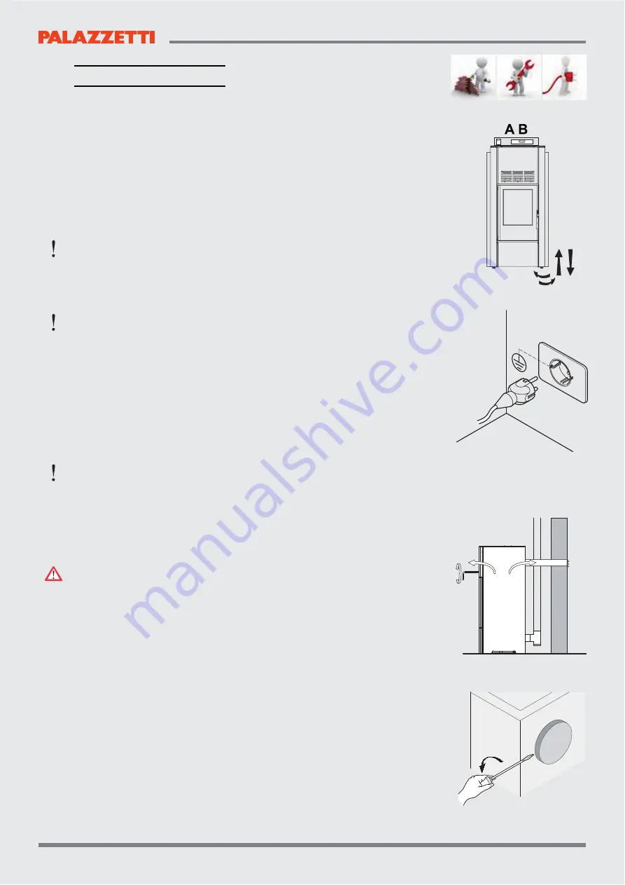
Fig. 6.1
Fig. 6.2
Fig. 6.4
Fig. 6.3
6 INSTALLATION
"
"
#$%"&'()%"*+&'",%"35&'699%:",;"<+693=%:">%?&(55%9"35"@(*>9365@%"B3'$"CD"EFGHJK
6.1 LEVELLING THE STOVE
The stove must be levelled by adjusting the feet (where featured), then checked
using a spirit level (Fig. 6.1).
A B
= Spirit level
6.2 SYSTEM CONNECTIONS
6.2.1 Electrical connection
The stove is connected to the electrical system simply using the plug supplied.
The electrical connection (plug) must be easily accessible when the stove is installed.
If the power cord is damaged it must be replaced by the technical service or a
<+693=%:"'%@$53@365Z"'(">?%)%5'"65;"[35:"(\"?3&[K
6.2.1.1 Earth
"
"
#$%" &;&'%*" *+&'" ,%" %6?'$%:" 65:" =''%:" B3'$" 6" ?%&3:+69" @+??%5'" @3?@+3'],?%6[%?" 35"
accordance with legislation in force (Fig. 6.2).
"
#$%"^+%"*+&'"$6)%"3'&"(B5"%6?'$"@(55%@'3(5K
6.2.1.2 Room thermostat
The thermostat is connected to the appropriate inputs of the circuit board, as shown
in the wiring diagram in the attached “Product Manual”.
6.2.1.3
!"#$%"&'"()*"&+$,-/&0$4&#$'"-5&78"4"&9%%"':
The remote device is connected to inputs 1 and 2 on terminal block CN7 on the
electronic board. (only in the board where terminal block CN7 has 10 inputs)
"
"
#$%" :%)3@%" *+&'" ,%" @(5=`+?%:" 6&" Dqxy{||}" q~CD" 65:" $6)%" 65" 6:+&'6,9%"
differential.
When activated (contact opens) the stove will be switched off or on.
!"#$%&'()#*++'(,&#-$&%$/0#$&5$7'8$9&#-$&)#07$&/:)#&;$&)#*%#$5&#-$&<%)#&#'/$&"%0/&
the control panel.
6.2.2 =0(($8#'0(�&*(&*'%&5')#%';:#'0(&)>)#$/
?0(+>&"0%&5:8#$5&/05$+)&0%&@%07'5$5&D'#-&5:8#'(,&J'#K
Ducted models can be connected to a hot air distribution system. The pipes used
should preferably be circular with a smooth inner surface and suitably insulated to
avoid heat loss.
P0%&5:8#$5&)#07$)&0%&/05$+)&%$*5>�&<#&*&5:8#'(,&J'#&#-*#&*%$&(0#&80(($8#$5&
#0&*&-0#&*'%&5')#%';:#'0(&@'@$9&/*J$&):%$&#-$&5$Q$8#0%&')&@0)'#'0($5&)0&*)�&
deviate the hot air into the room where the stove is installed.
D
UCTED
STOVES
"
"
&35`"'$%"'((9"&+>>93%:"(?"'$%"63?":%^%@'(?"9%)%?",6&%:"(5"'$%"*(:%9Z"'$%"^(B"(\"
hot air can be deviated from the room where the stove is installed to the ducting,
and vice-versa (Fig. 6.3).
To connect the stove to the ducting system, remove the cap by unscrewing the two
fastening screws that secure the duct closure cap on the rear of the stove (Fig. 6.4).
S
TOVES
READY
TO
FIT
A
DUCTING
KIT
To assemble the ducting kit see the instructions provided with the kit.
"
"
#$%" ^(B" (\" $('" 63?" @65" ,%" :%)36'%:" \?(*" '$%" ?((*" '(" '$%" :+@'35`" +&35`" '$%" '((9"
&+>>93%:"B3'$"'$%"[3'"'("6:+&'"'$%":%^%@'(?"@(5'?(9"9(@6'%:"(5"'$%"\?(5'"(\"'$%"&'()%K


