33
00 477 0152 -04/2017 - PALAZZETTI - PN - I
TALY
- 5.2 -
- 5.3 -
Z
B
A
X
X
β
90°
c
a
ENGLISH
INSTALLATION
4. he must wear safety shoes;
5. he must make sure that the area he is working in for
assembling/dismantling the
¿
replace is free from
obstacles.
5.3
FLUES AND CHIMNEY CAPS
The chimney must be dimensioned in compliance with
EN 13384-1.
Follow the indications in the technical data sheet relating
to the chimney draught.
The flue pipe for the discharge of smoke must be
compliant with standards EN 10683, EN 1856-1-2, EN
1857, EN 1443, EN 13384-1-3, EN 12391-1,
EN15287-1
both in terms of size and materials used to construct it.
• The
soot
¿
re resistance class of the chimney must be at least
T400.
•
A PERFECT DRAUGHT is above all the result of a
À
ue
that is clear of obstructions such as chokes, horizontal
sections or corners; any axial displacements should be
at a maximum angle of 45° compared to the vertical axis,
(better still if it is only 30°). These displacements should
preferably be effected near the chimney top.
•
THE SMOKE PIPE between the
¿
replace and the
À
ue pipe
must have the same cross-section as the appliance’s
smoke outlet. The smoke pipe must be sealed. It is
prohibited to use extendable
À
exible metal pipes. To
connect the appliance to the chimney, you may perform
a maximum of 3 direction changes no greater than 90°,
with the smoke pipe no longer than 2 m in horizontal
projection and a maximum of 3 total meters. Make sure
that the
¿
rst vertical segment is at least 50 cm before
changing direction.
•
The CHIMNEY TOP shall be the WINDPROOF type with an
inside cross section equivalent to that of the
À
ue and with
a smoke outlet passage section at least DOUBLE the
internal one of the
À
ue.
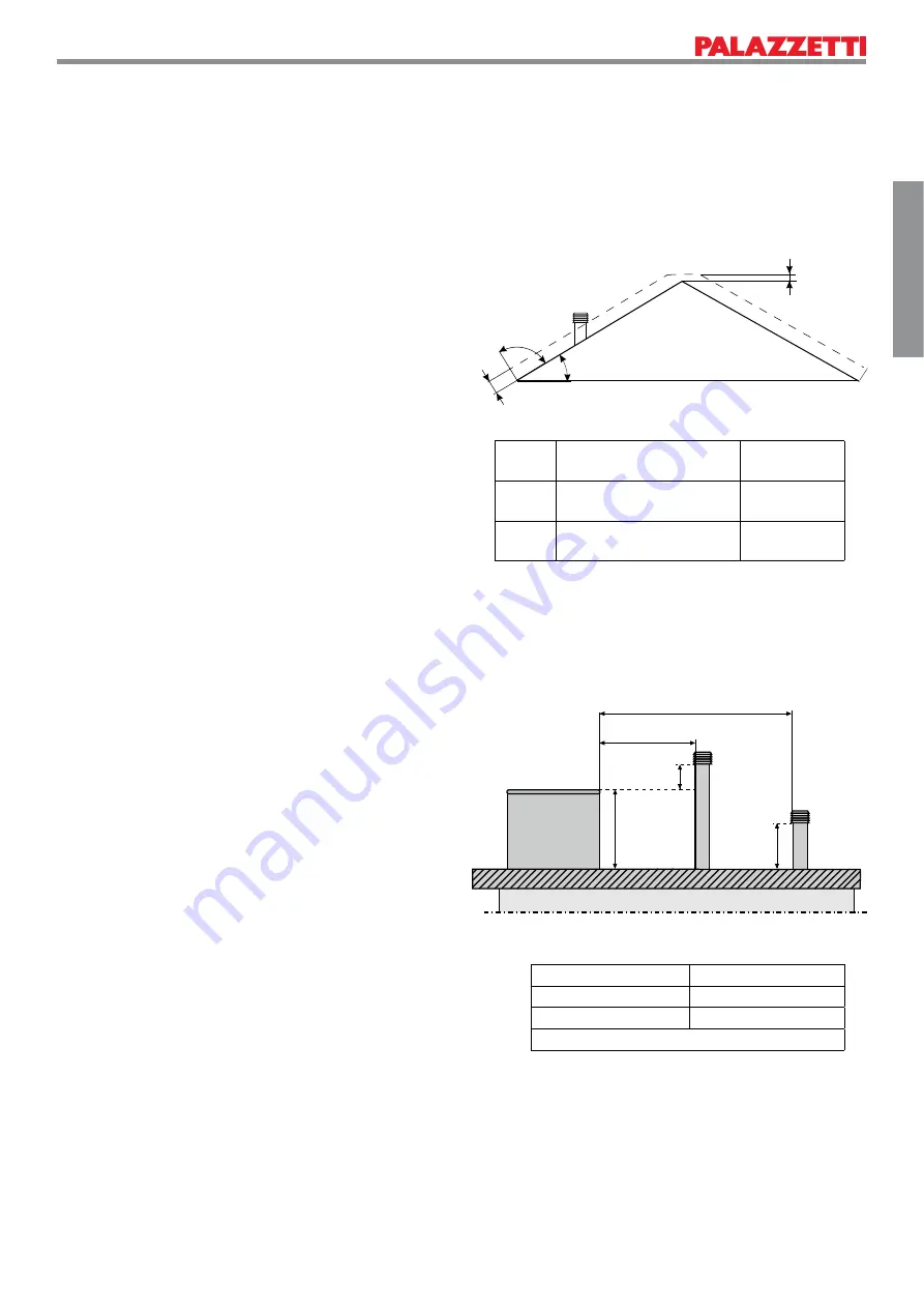
• Back
À
ow area: The outlet must be outside of the back
À
ow area
calculated according to
¿
gure 5.2 and relative table. Near
the ridge cap, consider the less of the two.
•
If there are obstacles on
À
at roofs, to position the chimney
respect the distances and measurements according to
¿
gure 5.3 and relative table.
If the
¿
replace is installed with a
À
ue that has already
been used it should be cleaned thoroughly to avoid
malfunctions and the danger of unburned parts deposited
on the inside from catching
¿
re.
Symbol Description
Buffer zone
(mm)
c
Distance measured 90° from
the roof surface
1300
a
Height above the roof ridge
cap
500
Distance (mm)
Outlet position
X
2000
Z + A
X > 2000
B
where A=500 and B=1000


