004778990 - 11/02/2022
51
ITALIANO
ENGLISH
DEUTSCH
FRANÇAIS
ESPAÑOL
7.6 Flue connection
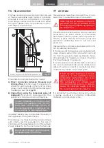
The flue connection must be tight and the use
of flexible extendible metal pipes is forbidden.
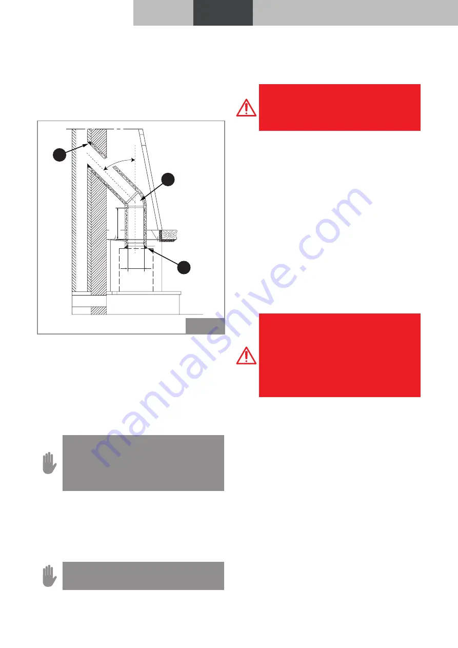
Changes in direction with respect to the appli-
ance flue gas outlet must be made with elbow
fittings no greater than 45° (preferably only 30°)
with respect to the vertical.
Ø D
H=
2D
max 45°
A
B
C
Product images are for illustrative purposes only
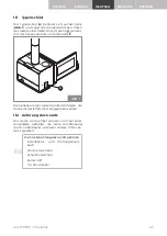
Fig. 13
The connection can be made in two ways:
a) Direct connection between ecopalex and
chimney flue.
In some cases, it is necessary to
adapt the existing hole in the hood (or make
a new one) in order to facilitate the passage of
the flue gas duct (
A - Fig. 13
).
b) connection using the telescopic pipe kit
(optional).
This solution can be used only if the
appliance is installed in existing fireplaces.
Correct installation of the fume duct
between the appliance and the fire-
place must be watertight, sealing all
the linking joints (
B, C - Fig. 13
) with ma-
terial suitable for high temperatures.
Imperfect sealing may compromise the safety of
the appliance and its performance.
The chimney cowl must be of the windproof type
with internal section equivalent to the one of
chimney and the passage section of the exhaust
smoke at least twice the one inside the flue pipe.
Do not insert draught butterfly regula-
tor diaphragms in the fitting.
7.7 air intake
The appliance must have the right flow of com-
bustion air to guarantee proper combustion.
There must be an outside air intake to
guarantee the flow of combustion air
to the appliance and/or recirculation of
the ambient air.
The outside air intake must be correctly sized and
protected by an insect screen. A non-closable
permanent protection grille must be placed ex-
ternally; in areas that are particularly windy and
exposed to weathering, install a rain and wind
protection.
Make sure the air intake is positioned so that it is
not accidentally obstructed.
If the rear wall of the appliance is an external wall,
make a hole to extract the combustion air 20-30
cm from the ground, observing the size indica-
tions indicated in “External air intake” of section
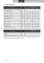
"Technical features" on page 45.
If it is not possible to create the fresh air intake in
the room, an external hole can be created in an
adjacent room provided it is permanently inter-
connected by means of a transfer grille.
If there are other heating or extraction
appliances in the installation room,
combustion malfunctions may occur
due to a lack of combustion air.
The combustion air intakes must
therefore be sized correctly, in order to
ensure the necessary supply of air for
the correct operation of all devices.
It is prohibited to withdraw combustion air from
a garage, warehouse containing combustible
materials or rooms at risk of fire.


