39
ENGLISH
INSTALLATION
6 INSTALLATION
7KHVWRYHPXVWEHLQVWDOOHGE\TXDOL¿HGSHUVRQQHO
in compliance with EN 10683.
6.1 LEVELLING THE STOVE
The stove must be levelled by adjusting the feet
(where featured), then checked using a spirit level
(Fig. 6.1).
6.2 SYSTEM
CONNECTIONS
6.2.1 Electrical
connection
The stove is connected to the electrical system
simply using the plug supplied.
The electrical connection (plug) must be easily
accessible when the stove is installed.
If the power cord is damaged it must be replaced
E\WKHWHFKQLFDOVHUYLFHRUDTXDOL¿HGWHFKQLFLDQ
to prevent any kind of risk.
6.2.1.1 Earth
7KH V\VWHP PXVW EH HDUWKHG DQG ¿WWHG ZLWK D
residual current circuit-breaker in accordance with
legislation in force (Fig. 6.2).
7KHÀXHPXVWKDYHLWVRZQHDUWKFRQQHFWLRQ
6.2.2 Installing the control panel
The stove’s control panel can be mounted into a
plasterboard wall by cutting a hole (105x60mm)
DQG ¿WWLQJ LWV PRXQWLQJ EUDFNHW LQFOXGHG WR LWV
EDFNZLWKWKHWZREROWV¿J
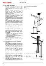
Do not install the panel in a hot area of the hood.
Run the cable between the panel and the stove in
such a way that it is not damaged by heat when the
stove is running.
The control panel hooks up with its cable to
connector RJ11.
¿J
Fig. 6.2
Fig. 6.1
Summary of Contents for MULTIFIRE BIO 14
Page 14: ...14 USO E MANUTENZIONE USO E MANUTENZIONE ...
Page 30: ......
Page 42: ...42 USE AND MAINTENANCE USE AND MAINTENANCE ...
Page 58: ......
Page 70: ...70 VERWENDUNG UND WARTUNG BEDIENUNGS UND WARTUNGSANLEITUNG ...
Page 86: ......
Page 98: ...98 EMPLOI ENTRETIEN USE AND MAINTENANCE ...
Page 114: ......
Page 126: ...126 USO Y MANTENIMIENTO USO Y MANTENIMIENTO ...
Page 142: ......
Page 143: ......


