48/172
cod. 00 477 2250 - 11/2013 - PN - Italy
INSTALLATION
6.2
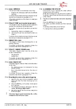
AIR INTAKE
The combustion air enters the stove compartment
from the air intake (
3
) and is drawn into the
combustion chamber through a duct located on the
rear part of the stove.
Make sure that the air intake is located in a way
that it cannot be obstructed by accident.
The UNI 10683 standard forbids the intake of
air for combustion from garages, rooms where
The external air intake hole must not be connected
to the stove by pipes.
If there are other heating units in the room,
the combustion air intakes must ensure the
required volume of air for proper operation of
all devices.
In case in the room where the stove is installed
there are one or more extractors (such as kitchen
aspirators), some troubles to the combustion due
to the lack of comburent air might occur.
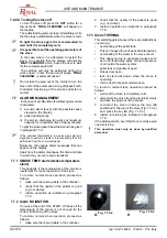
6.3 ASSEMBLY
DIAGRAM
Assembly must be carried out by qualified
personnel.
1. Seal
2.
w!
3. &
4.
of the cladding.
5. Flame-retardant counter hood and load-
bearing structure
6. Y _
retardant material
7. Minimum distance of 1 cm between cladding
and Fireplace
8. *w
minimum distance of 20 cm.
The minimum clearance between the stove and
ignitable materials must be 20 cm.
The minimum distance from combustible
materials must be 20 cm.
To ensure correct installation, the smoke pipe
w
!
If the fireplace is installed with a flue that
it should be cleaned thoroughly to avoid
malfunctions and the danger of unburned parts
!
Improper installation may compromise the
safety of the unit. It must be possible for
stove when it is not in operation.
'
it must not have any removable parts, so that
electrically powered and moving parts are not
accessible by the user.
6.4 PELLETS
LOADING
#
the hood and connected to the appliance by
__!}
assembly instructions contained in the package.
We recommend using only original accessories.
The fall of pellets outside the tank could cause
!
1
2
3
4
5
6
7
Fig. 6.2.1