background image

ITALIANO

ENGLISH

DEUTSCH

FRANÇAIS

ESPAÑOL

004778230 - 15/04/2020   

33

6  OPERATION

6.1  Hydraulic system

The hydraulic system and the appliance itself must be connected by qualified personnel in compli-

ance with laws and regulations in force in the country (in Italy ref. D.M. 1/12/1975 and UNI 10412-2). The 

hydraulic connection to the appliance must be made before the upper part of the casing and the 

outer hood are installed.
1. 

Before installing the casing, perform the hydraulic seal test on the pipes connected to the 

appliance.
2. 

Make sure that all control and safety devices, including those supplied as standard, have been 

installed correctly.

Make sure that, when the stove is in use, all conditions allowing the system to absorb the 

heat generated safely are in place.

MAIN CIRCUIT: OPEN CHAMBER
MAXIMUM SECONDARY CIRCUIT PRESSURE: 2.5 bar

DO NOT INCLUDE any room thermostats that stop or start the circulation pump in order 

to regulate the temperature in rooms. For safety reasons, the pump must ALWAYS operate 

for as long as the stove is burning fuel, to dispose of the heat generated in the Termopalex. 

If the rooms are too hot, reduce the size of the fire, even letting it go out if necessary.

Never exceed the maximum recommended load of wood fuel indicated in the product booklet.

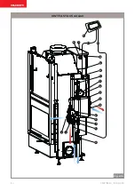
Description of the hydraulic connections  

(Fig. 6.1a)


The hydraulic unit comprises the following parts:
A) Circulator (main circuit)
B) Circulator (secondary circuit)
C) Plate-type heat exchanger
D) Digital thermo-regulator
E) Main circuit delivery with cut-off valve
F) Manual secondary circuit vent
G) Expansion chamber open
H) Main circuit drain tap
I) Secondary circuit delivery with cut-off valve
J) Main circuit return cut-off valve
K) Secondary circuit safety valve (2.5 bar)
L) Secondary circuit filling/emptying
M) Probe well
N) Mains water inlet
O) Expansion chamber discharge
P) ACS mixing/delivery valve
Q) Top-up pipe connection
R) Main circuit top-up pipe
S) Secondary circuit return cut-off valve

Connection to the water circuit

The stove is connected to the water circuit at the 

following points:
•  Hot water delivery to secondary circuit (I)
•  Return from secondary circuit (J)
•  Mains water inlet (N)
•  ACS mixing/delivery valve (P)
•  Expansion chamber discharge (O)
•  Secondary circuit filling/emptying (L)
•  Secondary circuit safety valve discharge (K)
•  Appliance boiler discharge (H)

Probe connection

Connect the two probes of the temperature 

controller (S1 and S2). Insert S1 in the housing 

(M) on the fireplace. Place S2 on the secondary 

return pipe, near the shut-off valve (S).  

Digital temperature controller (ACS) 

configuration

Set the digital temperature controller according 

to “system diagram n°17”.
Set parameter A25 of the GLH 110 to 48°.
Follow the instructions in the temperature 

controller manual.

HWT FAST ACS version

Summary of Contents for TERMOPALEX HWT

Page 1: ...NGSANLEITUNGEN Die vorliegende Anleitung ist fester Bestandteil des Produkts Vor der Installation Wartung und Verwendung die Anleitu gen stets aufmerksam durchlesen NOTICE D UTILISATION ET D ENTRETIEN...

Page 2: ...ns gew hrten Vorzug danken und Ihnen zur Wahl gratulieren Damit Sie Ihren neuen Termopalex so gut wie m glich benutzen k nnen bitten wir Sie die in dieser Bedienungs und Wartungsanleitung enthaltenen...

Page 3: ...tricola 5 1 12 Consegna dell apparecchio 5 2 AVVERTENZE PER LA SICUREZZA 6 2 1 Avvertenze per l utilizzatore 6 3 CARATTERISTICHE DEL COMBUSTIBILE 6 4 ACCENSIONE 7 4 1 Prima accensione 7 4 2 Accensione...

Page 4: ...ancanza di esperienza o di conoscenza a meno che esse abbiano potuto beneficiare attraverso l intermediazione di una persona responsabile della loro sicurezza di una sorveglianza o di istruzioni rigua...

Page 5: ...rezza modifiche e o riparazioni non autorizzate dal costruttore effettuate sul prodotto carenza di manutenzione eventi eccezionali 1 9 Assistenza tecnica e manutenzione Palazzetti mette a disposizione...

Page 6: ...stessa e o compromettere la stabilit dell apparecchio Non usare l apparecchio come supporto od an coraggio di qualunque tipo Non pulire l apparecchio fino a completo raffred damento di struttura e cen...

Page 7: ...pongono il prodotto La resa nominale in kW dell apparecchio si ottie ne bruciando una corretta quantit di legna fa cendo attenzione a non sovraccaricare la camera di combustione La legna deve avere un...

Page 8: ...uoco ed assicurarsi che sia ben chiusa 8 Mantenere la presa d aria aperta per garantire una fiamma alta e luminosa A Fig 4 2b 9 Ridurrel aperturadellapresad aria B Fig 4 2b utilizzando l apposita mani...

Page 9: ...vetro si effettua con un panno umido o con della carta inumidita e passata nella cenere Per effettuare la pulizia del vetro necessario aprire la porta a Vasistas tirando verso l esterno la o le manigl...

Page 10: ...distribu tore aria comburente al fine di evitare eventuali accumuli di cenere B Fig 5 2b Riporre la griglia con massima cautela su un piano d appoggio adeguato L uso di un aspiracenere pu semplificare...

Page 11: ...i prodotto ri volgendosi a personale specializzato 5 4 Manutenzione del giro fumi Anche nel caso dei tubi di scambio e dei turbolatori si consiglia di effettua re la pulizia almeno una volta all anno...

Page 12: ...sollevare leggermente i turbolatori inseriti nei tubi di scambio ed estrarre la spina in metallo che li tiene vincolati nella loro posizione Fig 5 4h Pulire i tubi di scambio con lo scovolo in dota z...

Page 13: ...004778230 15 04 2020 ITALIANO ENGLISH DEUTSCH FRAN AIS ESPA OL 13 Fig 5 4i Fig 5 4j Fig 5 4k Fig 5 4l...

Page 14: ...Fig 6 1a Laparteidraulica costituitadaiseguentielementi A Circolatore circuito primario B Circolatore circuito secondario C Scambiatore a piastre D Termoregolatore digitale E Mandata circuito primario...

Page 15: ...004778230 15 04 2020 ITALIANO ENGLISH DEUTSCH FRAN AIS ESPA OL 15 C P N K B L I J S H M E Q R O G S1 S2 F A D Fig 6 1a versione HWT FAST ACS...

Page 16: ...so di Espansione S Valvola d intercettazione del ritorno del circuito secondario Allacciamento all impianto Il termocamino allacciato all impianto attraver so i seguenti punti Mandata acqua calda al c...

Page 17: ...004778230 15 04 2020 ITALIANO ENGLISH DEUTSCH FRAN AIS ESPA OL 17 S1 S2 D C M E N F A O G L I H K B J S Fig 6 1b versione HWT FAST...

Page 18: ...ostituitadaiseguentielementi G Vaso di espansione aperto N Ingresso acquedotto O Scarico vaso di Espansione Allacciamento all impianto Il termocamino allacciato all impianto attraver so i seguenti pun...

Page 19: ...eneri che dell acqua calda domestica La funzione an tiscottatura consiste nel miscelare l acqua calda prodotta dallo scambiatore con quella fredda al fine di garantire una temperatura costante alla co...

Page 20: ...I ACCENSIONE OGNI ANNO Griglia X Cassetto Vano cenere X Vetro X Guarnizioni portina X Condotto di evacuazioni fumi X Scambiatore e giro fumi X Turbolatori X Impianto idraulico X A cura di un tecnico a...

Page 21: ......

Page 22: ...24 1 11 Serial number and ID plate 24 1 12 Delivery of the equipment 24 2 SAFETY WARNINGS 25 2 1 Warnings for users 25 3 FUEL CHARACTERISTICS 25 4 IGNITION 26 4 1 First use 26 4 2 Ignition 27 4 3 Addi...

Page 23: ...tal capacities are impaired or who or lack experience or knowledge unless they re ceive surveillance or instruction concerning the use of the appliance by a person responsible for their safety The ind...

Page 24: ...qualified and or untrained personnel use not compliant with safety directives modifications and or product repairs not au thorised by the manufacturer lack of maintenance exceptional events 1 9 Techni...

Page 25: ...t lean on the open door during cleaning operations this could cause the door to break and or may compromise the stability of the appliance Do not use the appliance as a support or anchor in any way wh...

Page 26: ...ave a recommended moisture content no higher than 25 and an ideal length of about 33 cm It must be arranged horizontally taking care not to completely obstruct the slots on the fireplace grill and the...

Page 27: ...re lighter from the top 7 Close the fire door and make sure it is firmly locked in place 8 Keep the air inlet open to ensure a high bright flame A Fig 4 2b 9 Only reduce the air inlet aperture B Fig 4...

Page 28: ...glass Clean the glass with a damp cloth or damp paper passed in the ashes To clean the glass open the dual aperture door by pulling the handle s outwards to release the locking pin on the upper side...

Page 29: ...erneath A Fig 5 2b Vacuum the front and rear holes of the combus tive air distributor to prevent any accumulation of ash B Fig 5 2b Place the grill on a suitable surface with great care Using an ash v...

Page 30: ...act specialised personnel 5 4 Fume coil maintenance It is also advisable to clean the heat exchange coils and turbulators at least once a year or every 4000 kg of wood burnt as specified in the prod u...

Page 31: ...w B Fig 5 4g To slide out the turbulators from above lift the tur bulators inserted in the heat exchange coil just a little and extract the metal retainer pin Fig 5 4h Clean the heat exchange coil wit...

Page 32: ...32 004778230 15 04 2020 Fig 5 4i Fig 5 4j Fig 5 4k Fig 5 4l...

Page 33: ...scription of the hydraulic connections Fig 6 1a The hydraulic unit comprises the following parts A Circulator main circuit B Circulator secondary circuit C Plate type heat exchanger D Digital thermo r...

Page 34: ...34 004778230 15 04 2020 C P N K B L I J S H M E Q R O G S1 S2 F A D Fig 6 1a HWT FAST ACS version...

Page 35: ...O Expansion chamber discharge S Secondary circuit return cut off valve Connection to the water circuit The stove is connected to the water circuit at the following points Hot water delivery to second...

Page 36: ...36 004778230 15 04 2020 S1 S2 D C M E N F A O G L I H K B J S Fig 6 1b HWT FAST version...

Page 37: ...the hydraulic connections Fig 6 1c The hydraulic unit comprises the following parts G Expansion chamber open O Expansion chamber discharge N Mains water inlet Connection to the water circuit The stove...

Page 38: ...tic hot water applications The anti scald function mixes hot water generated by the heat exchanger with cold water in order to ensure constant tempera ture on delivery 7 2 Thermostatic mixer The therm...

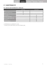
Page 39: ...ontrol and maintenance schedule EVERY USE EVERY YEAR Grill X Ash drawer compartment X Glass X Door gaskets X Fume evacuation duct X Heat exchanger and fume coil X Turbulators X Hydraulic system X Perf...

Page 40: ......

Page 41: ...zteile 43 1 11 Typenschild 43 1 12 Lieferung des Ger ts 43 2 SICHERHEITSHINWEISE 44 2 1 Hinweise f r den Benutzer 44 3 EIGENSCHAFTEN DES BRENNSTOFFS 44 4 ANFEUERUNG 45 4 1 Erste Anfeuerung 45 4 2 Anfe...

Page 42: ...k rperliche sensorische oder mentale F higkeiten eingeschr nkt sind oder denen es an Erfahrung oder Wissen mangelt es sei denn sie konnten durch Vermittlung einer f r ihre Sicherheit verantwortlichen...

Page 43: ...gen Installation durch nicht qualifiziertes und oder nicht geschultes Personal nicht den Sicherheitsvorschriften entsprechen de Verwendung nicht durch den Hersteller genehmigten nde rungen und oder Re...

Page 44: ...ht als St tze oder Verankerung jeglicher Art Reinigen Sie das Ger t nicht solange die Kons truktion und die Asche nicht vollst ndig abge k hlt sind F hren Sie alle Arbeiten mit maximaler Sicher heit u...

Page 45: ...aus denen das Produkt besteht Die Nennleistung des Ger ts in kW wird erzielt wenn eine ordnungsgem e Brennholzmenge verbrannt wird Es darauf zu achten dass die Brennkammer nicht berladen wird Das Bren...

Page 46: ...sie gut geschlossen ist 8 Den Lufteinlass offen halten um eine hohe und helle Flamme zu gew hrleisten A Abb 4 2b 9 Die Lufteinlass ffnung erst dann mithilfe des kalten Griffs verkleinern B Abb 4 2b we...

Page 47: ...inem feuchten Tuch oder mit befeuchtetem Papier das in die Asche getaucht wird ausgef hrt Zum Reinigen des Glases muss die Kippt r ge ffnet werden Hierzu den oder die Griffe nach au en ziehen um den V...

Page 48: ...nd hinteren ffnungen des Verbrennungsluftverteilers absaugen um m gliche Ascheansammlungen zu vermeiden B Abb 5 2b Den Rost ganz vorsichtig auf einer ge eigneten Ablagefl che ablegen Die Verwendung ei...

Page 49: ...achpersonal durchf hren zu lassen 5 4 Wartung der Windungen Auch bei den Tauscherrohren und den Turbolatoren wird empfohlen mindes tens einmal j hrlich oder nach jeweils 4 000 kg Brennholzverbrauch di...

Page 50: ...sziehen von oben die in Tau scherrohre eingesetzten Turbolatoren leicht anheben und den Metallstift herausziehen der sie in ihrer Position festh lt Abb 5 4h Die Tauscherrohre mit der mitgelieferten B...

Page 51: ...ITALIANO ENGLISH DEUTSCH FRAN AIS ESPA OL 004778230 15 04 2020 51 Abb 5 4i Abb 5 4j Abb 5 4k Abb 5 4l...

Page 52: ...die im Produkt heft angef hrt ist Beschreibung der Wasseranschl sse Abb 6 1a Der hydraulische Teil besteht aus folgenden Elementen A Umw lzpumpe Prim rkreislauf B Umw lzpumpe Sekund rkreislauf C Plat...

Page 53: ...ITALIANO ENGLISH DEUTSCH FRAN AIS ESPA OL 004778230 15 04 2020 53 C P N K B L I J S H M E Q R O G S1 S2 F A D Abb 6 1a version HWT FAST ACS...

Page 54: ...l am R cklauf des Sekund rkreises Anschluss an die Anlage Der Thermokamin wird ber folgende Punkte an die Anlage angeschlossen Warmwasservorlauf am Sekund rkreis I R cklauf vom Sekund rkreis J Wasserv...

Page 55: ...ITALIANO ENGLISH DEUTSCH FRAN AIS ESPA OL 004778230 15 04 2020 55 S1 S2 D C M E N F A O G L I H K B J S version HWT FAST Abb 6 1b...

Page 56: ...Teil besteht aus folgenden Elementen G Offenes Ausdehnungsgef N Wasserversorgungseingang O Ablass Ausdehnungsgef Anschluss an die Anlage Der Thermokamin wird ber folgende Punkte an die Anlage angeschl...

Page 57: ...ion f r allgemeine Warm wasseranwendungen f r den h uslichen Ge brauch Die Verbr hschutzfunktion besteht in der Mischung des vom W rmetauscher er zeugten Warmwassers mit dem Kaltwasser um eine konstan...

Page 58: ...mm JEDE ANFEUERUNG JEDES JAHR Rost X Aschenlade Aschenraum X Glas X T rdichtungen X Rauchabzugsrohr X Tauscher und Windungen X Turbolatoren X Hydraulikaggregat X Durch einen befugten Techniker Mindest...

Page 59: ......

Page 60: ...pareil 62 2 CONSIGNES DE S CURIT 63 2 1 Avertissements pour l utilisateur 63 3 CARACT RISTIQUES DU COMBUSTIBLE 63 4 ALLUMAGE 64 4 1 Premier allumage 64 4 2 Allumage 65 4 3 Ajout du combustible 65 5 NE...

Page 61: ...es dont les capacit s physiques sensorielles ou mentales sont r duites ou qui manquent d ex p rience ou de connaissances sauf s ils ont pu b n ficier d une surveillance ou de consignes d utilisation d...

Page 62: ...parations non autoris es par le fabricant sur le produit manque d entretien v nements exceptionnels 1 9 Assistance technique et entretien Palazzetti fournit un r seau dense de centres d assistance ave...

Page 63: ...re de la porte et ou compromettre la stabilit de l appareil Ne pas utiliser l appareil comme support ou an crage d aucune sorte Ne pas nettoyer l appareil tant que la structure et les cendres ne sont...

Page 64: ...oque une d t rioration sou daine des composants internes du produit La puissance nominale en kW de l appareil est obtenue en br lant une quantit correcte de bois en prenant soin de ne pas surcharger l...

Page 65: ...coupe feu et s assurer qu elle est bien ferm e 8 Garder la prise d air ouverte pour assurer une flamme haute et brillante A Fig 4 2b 9 R duire l ouverture de la prise d air B Fig 4 2b en utilisant la...

Page 66: ...humide ou avec du papier humide et pass dans la cendre Pour nettoyer la vitre il est n cessaire d ouvrir la porte en vasistas en tirant la ou les poign es vers l ext rieur pour lib rer le doigt de ver...

Page 67: ...arri re du distributeur d air de combustion pour viter toute accumulation de cendres B Fig 5 2b Placer soigneusement la grille sur un plan d appui appropri L utilisation d un aspirateur cendres peut...

Page 68: ...en contac tant du personnel sp cialis 5 4 Entretien du circuit des fum es Dans le cas des tuyaux d change et des turbulateurs galement il est conseill de nettoyer au moins une fois par an ou tous les...

Page 69: ...ar le bas B Fig 5 4g Pour extraire les turbulateurs par le haut sou lever l g rement les turbulateurs ins r s dans les tubes d change et retirer la goupille m tallique qui les maintient bloqu s dans l...

Page 70: ...70 004778230 15 04 2020 Fig 5 4i Fig 5 4j Fig 5 4k Fig 5 4l...

Page 71: ...s hydrauliques Fig 6 1a La partie hydrauliques est compos e des l ments suivants A Circulateur dans circuit primaire B Circulateur dans circuit secondaire C changeur plaques D Thermor gulateur num riq...

Page 72: ...72 004778230 15 04 2020 C P N K B L I J S H M E Q R O G S1 S2 F A D Fig 6 1a version HWT FAST ACS...

Page 73: ...d expansion S Vanne d arr t du retour du circuit secondaire Connexion au syst me Le po le chemin e est connect au syst me via les points suivants Refoulement d eau chaude vers le circuit se condaire...

Page 74: ...74 004778230 15 04 2020 S1 S2 D C M E N F A O G L I H K B J S Fig 6 1b version HWT FAST...

Page 75: ...accords hydrauliques Fig 6 1c La partie hydrauliques est compos e des l ments suivants G Vase d expansion ouvert N Entr e aqueduc O Vidange vase d expansion Connexion au syst me Le po le chemin e est...

Page 76: ...n rales d eau chaude sanitaire La fonction anti br lure consiste m langer l eau chaude produite par l changeur avec l eau froide afin de garantir une temp rature constante la distribution 7 2 Mitigeu...

Page 77: ...d entretien CHAQUE ALLUMAGE TOUS LES ANS Grille X Tiroir compartiment des cendres X Vitre X Joint de porte X Conduit d vacuation des fum es X changeur et circuit des fum es X Turbulateurs X Circuit hy...

Page 78: ......

Page 79: ...Entrega del aparato 81 2 ADVERTENCIA PARA LA SEGURIDAD 82 2 1 Advertencias para el usuario 82 3 CARACTER STICAS DEL COMBUSTIBLE 82 4 ENCENDIDO 83 4 1 Primer encendido 83 4 2 Encendido 84 4 3 Llenado...

Page 80: ...entales reducidas o inexpertas sin la supervisi n o instrucciones en cuanto al uso del aparato mismo por parte de una persona responsable de su seguridad El destino de uso indicado es v lido nicamente...

Page 81: ...o y o no debidamente formado Uso no conforme con las directivas de seguridad Modificaciones y o reparaciones no autorizadas por el fabricante efectuadas en el producto Carencia de mantenimiento Hechos...

Page 82: ...erta abierta se puede provocar la rotura de la puerta mismay ocomprometerlaestabilidaddelaparato No use el aparato como soporte o anclaje de ning n tipo No limpie el aparato hasta que se enfr en por c...

Page 83: ...nte rica en aceites arom ticos p ej eucalipto mirto etc provo ca el deterioro repentino de los compo nentes internos del producto El rendimiento nominal del aparato expresado en kW se obtiene quemando...

Page 84: ...e bien cerrada 8 Mantenga la toma de aire abierta para garan tizar una llama alta y luminosa A Fig 4 2b 9 Reduzca la apertura de la toma de aire B Fig 4 2b con la correspondiente manilla fr a solo cua...

Page 85: ...pieza del vidrio se realiza con un pa o h medo o con papel humedecido y pasado por la ceniza Para efectuar la limpieza del vidrio se debe abrir la puerta basculante tirando hacia fuera la o las manill...

Page 86: ...idor del aire comburente para evitar posibles acumulaciones de ceniza B Fig 5 2b Ponga la parrilla con sumo cuida do sobre una superficie de apoyo adecuada El uso de un aspirador de cenizas puede faci...

Page 87: ...urriendo a personal especializado 5 4 Mantenimientodelarepisadehumos Tambi n en el caso de los tubos de intercambio y de los turbuladores se recomienda efectuar la limpieza al menos una vez al a o o b...

Page 88: ...buladores por la parte de arriba levante ligeramente los turbuladores en sartados en los tubos de intercambio y extraiga el v stago met lico que los fija en sus respecti vas posiciones Fig 5 4h Limpie...

Page 89: ...ITALIANO ENGLISH DEUTSCH FRAN AIS ESPA OL 004778230 15 04 2020 89 Fig 5 4i Fig 5 4j Fig 5 4k Fig 5 4l...

Page 90: ...onsta de los siguientes elementos A Circulador en circuito primario B Circulador en circuito secundario C Intercambiador de placas D Termorregulador digital E Impulsi n del circuito primario con v lvu...

Page 91: ...ITALIANO ENGLISH DEUTSCH FRAN AIS ESPA OL 004778230 15 04 2020 91 C P N K B L I J S H M E Q R O G S1 S2 F A D Fig 6 1a versi n HWT FAST ACS...

Page 92: ...V lvula de corte del retorno del circuito secundario Conexi n a la instalaci n La termochimenea se conecta a la instalaci n mediante los siguientes puntos Impulsi n de agua caliente al circuito secun...

Page 93: ...ITALIANO ENGLISH DEUTSCH FRAN AIS ESPA OL 004778230 15 04 2020 93 S1 S2 D C M E N F A O G L I H K B J S Fig 6 1b versi n HWT FAST...

Page 94: ...s siguientes elementos G Dep sito de expansi n abierto N Entrada en el acueducto O Descarga del dep sito de expansi n Conexi n a la instalaci n La termochimenea se conecta a la instalaci n mediante lo...

Page 95: ...maduras para apli caciones generales del agua caliente dom stica La funci n antiquemaduras consiste en mezclar el agua caliente que produce el intercambiador con el agua fr a para garantizar una tempe...

Page 96: ...CADA A O Parrilla X Caj n compartimento de cenizas X Vidrio X Juntas de la puertecilla X Conducto de evacuaci n de humos X Intercambiador y repisa de humos X Turbuladores X Sistema hidr ulico X A car...

Page 97: ......

Page 98: ......

Page 99: ......

Page 100: ...in this handbook and is free to modify the features of its products without prior notice Die Firma Palazzetti bernimmt f r eventuelle Fehler in diesem Heft keine Verantwortung und beh lt sich das Rech...

Reviews: