background image


Installation Dimensions


Revision 1.3 


- 8 - 

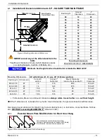
Installation Dimensions

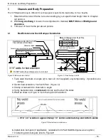
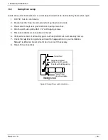
Do not weld across the corner posts

No weld
areas

No weld
areas

Figure 2 Chassis Dimension sheet for special requests


Summary of Contents for ILP

Page 1: ...ritos CA 90703 Tel 888 774 5844 Fax 562 924 8318 PALFINGER Liftgates LLC 572 Whitehead Road Trenton NJ 08619 Tel 609 587 4200 Fax 609 587 4201 Visit our website at www palfinger com for up to date information and notifications If you received this product with damaged or missing parts Please contact PALFINGER Liftgates at 888 774 5844 ...

Page 2: ...s Unloaded Truck 900mm Arm 14 5 Chassis and Body Preparation 15 5 1 Bed Extension Dock Bumper Installation 15 6 Gate and Platform Installation 16 6 1 Frame Installation 16 6 2 Gate Installation Using Liftarm Pins Platform Not Installed 18 6 2 1 Platform Installation 19 6 3 Tension on the spring 20 7 Electrical Installation 21 7 1 Main Power Connections 21 7 2 Circuit Breaker 21 7 3 UP DOWN Switch ...

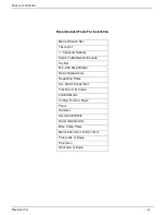
Page 3: ...ll To Medium Bottle Jack Pry Bar Min 250 Amp Welder Basic Screwdrivers Snap Ring Pliers Sm Metric Socket Set Forklift or O H Crane 3 8 Drill Motor Cutting Torch or Equiv Pliers Hammer Assorted Drill Bits Hand Held Grinder Wire Crimp Pliers Metric Allen Set 1 5mm 10mm Floor Jack or Equiv Paint Gun Heat Gun or Equiv ...

Page 4: ...ures CAUTION without the safety alert symbol is used to address practices not related to personal injury In this manual we use it to alert you to potentially hazardous situation which if not avoided may result in property damage CAUTION indicates a potentially hazardous situation which if not avoided may result in minor or moder ate injury WARNING indicates potentially hazardous situation which if...

Page 5: ...m Mount Frame Center of Gravity 2 Gate Overview and Components Figure 1 Liftgate overview with component description A liftgate contains three 3 main objectives 1 Foldable platform with shackles and coil springs 2 Lift arm assembly with parallel arms and lift cylinder 3 Main frame with roll over assembly and power pack enclosure Rubber Snubber ...

Page 6: ...ock bolts are tight 9 Grease all pivot points 10 Verify that ALL decals are placed properly Contact PALFINGER Liftgates to replace any missing decals 11 Final Check Off Sheet at rear of this manual MUST be filled out and kept in your records for future reference 12 Refer to owner s manual for troubleshooting repairs Important Dimensions Refer to line drawing on following pages 1 BED HEIGHT H Bed H...

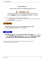
Page 7: ...than what s allowed the sill has to be notched and capped to achieve original strength Bend flat bar and weld 100 around the notch Minimum bed height dimensions are ALWAYS MAXIMUM LOADED TRUCK Floor Height Ranges Max Unloaded Min Loaded Installing a gate at or close to minimum bed height normally results in a gate that will NOT open and close from stored position if the floor height goes below min...

Page 8: ...Installation Dimensions Revision 1 3 8 4 Installation Dimensions Donotweldacrossthecornerposts Noweld areas Noweld areas Figure 2 Chassis Dimension sheet for special requests ...

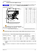
Page 9: ...latform Bed Height F Dimension Cut out X vertical Cut out Y horizontal Mount Clearance can be shortened by 5 Ground Clearance 38 to 47 5 22 12 17 5 38 5 12 to 20 40 to 48 5 23 14 16 5 37 5 13 to 20 42 to 50 25 15 5 15 35 13 to 20 44 to 52 5 27 17 5 13 5 33 13 to 20 46 to 53 29 19 5 12 5 32 13 to 20 F dimension Mount and Ground Clearance always relate to each other on a set floor height If the F di...

Page 10: ... 17 1 2 12 12 16 1 2 800 mm 15 12 15 1 2 12 19 1 2 Min laden bed height Max bedheight 43 1 2 53 51 47 1 2 31 1 2 Basic frame cut out and installation information ILP 800 mm 48 P F Bedheights covered 38 43 47 51 and 53 Assuming 22 F Dim Assuming 23 F Dim Assuming 27 F Dim Assuming 25 F Dim Assuming 29 F Dim 12 14 17 1 2 13 1 2 12 1 2 Figure 5 Frame cap suggestions related to bed height 800mm ...

Page 11: ...mensions STAY WITH THE F DIMENSION Minimum bed height is when truck trailer is loaded to MAX GVW Mounting Dimensions ILP with 800 mm 31 5 arm 48 1200 mm platform Bed Height F Dimension Cut out X vertical Cut out Y horizontal Mount Clearance Ground Clearance 38 to 47 5 22 12 17 5 38 5 12 to 20 40 to 48 5 23 14 16 5 37 5 13 to 20 42 to 50 25 15 5 15 35 13 to 20 44 to 52 5 27 17 5 13 5 33 13 to 20 46...

Page 12: ...12 16 1 2 13 1 2 800 mm 15 12 15 1 2 13 12 19 1 2 Min laden bed height Max bedheight 43 1 2 53 51 47 1 2 31 1 2 Basic frame cut out and installation information ILP ROUND TUBE Bedheights covered 38 43 47 51 and 53 Assuming 22 F Dim Assuming 23 F Dim Assuming 27 F Dim Assuming 25 F Dim Assuming 29 F Dim 12 14 1 2 15 1 2 Figure 7 Frame cap suggestions related to bed height ...

Page 13: ...ce F Dimension 45 15 26 46 16 26 47 17 26 48 18 26 49 19 26 50 20 26 51 20 27 52 20 27 5 53 21 27 5 54 21 29 55 21 5 29 5 Minimum Maximum Dimensions Suggested Mounting Dimensions Minimum bed height is when truck trailer is loaded to MAX GVW all dimensions in inches Mounting Dimensions ILP 54 1375 mm and 60 1525 mm platform with 900mm arm Bed Height F Dimension Cut out X vertical Cut out Y horizont...

Page 14: ... 45 47 51 and 55 Use the closest to your application These dimensions are starting points Your final dimensions may vary depending on actual installation F Dim Refer to chapter 3 and 4 Assuming 28 F Dim 12 12 12 900 mm 35 1 2 2 x3 x3 16 Angle 1 4 x3 HR Flat Frame Cap Not Supplied Not Supplied 15 3 4 22 1 4 17 21 1 2 12 18 1 4 21 19 1 2 20 1 2 Cut out vertical Cut out horizontal Figure 9 Frame Cap ...

Page 15: ...With Channel or Equiv 3 Channel A Channels Shipped with 45 angle on each side A A Bed Height Bumper 44 and Above 24 43 and Below 20 Note 20 Bumpers Have Single Step Interlift 12 Bumpers might need notching in some cases 3 16 3 16 3 16 12 12 Figure 10 Bed extension install Figure 11 Dock bumper install 1 Tack weld channels or angle 2 to rear sill not supplied only temporarily if possible use clamps...

Page 16: ...tory tack welds on each side at the lower knuckles are secure 6 Set mount plates in place and tack weld using 3 fillet welds 2 long on each side of mount plate and on top of mount plate Make sure to connect BODY LONG RAIL to mount plate if necessary extend mount plate with flat bar to reach BODY LONG RAIL The mount plate should be flat on the channel 7 Connect 2 Ga battery cable to truck battery a...

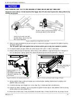
Page 17: ... 100 Fig 12 Figure 15 Platform roll over wheel adjustment Figure 16 Frame captioning for tight storage of liftgate 14 Verify platform lowers without hanging up on wheel before welding Slide wheel in slightly until platform lowers smoothly 15 Install frame caps per chapter 4 2 or 4 6 See Fig 14 alternate frame modification 16 Adjust 2 rubber snubbers up to force platform against frame caps to hold ...

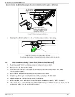
Page 18: ...llation Using Liftarm Pins Platform Not Installed 1 Place lift gate WITHOUT platform securely on rolling cart or equivalent 2 Slide gate on cart underneath vehicle 3 Lift mount frame assembly until upper lift arm bushings are able to align with mount holes in bed extension gussets 4 Slide upper lift arm pins through bed extension holes and lift arms 5 Using floor jack or equiv to swing frame assem...

Page 19: ...not slide so far that triangle block or spring fall out 4 Lift platform to lift arms with forklift or equiv 5 Rotate coil spring away from 8x80mm bolt so there is no tension during gate installation 6 Align lift arms into clevises and drive pin until pin tab seats in pin tab hole and install pin bolt and tighten to 14 ft lbs Short leg against tab Curb Side LOOKING Rear Liftarm Clevis Triangle Bloc...

Page 20: ...e shipping position of the spring arm b Fold up the platform and lower down the gate to the ground c Flip over the platform into stored position ATTENTION platform is heavy d Partially remove the parallel arm pin as shown and reorient the spring Slide the pin back and tighten up lock nut e Fold and unfold the platform and feel the assistance of the spring If it is still too heavy add weld to the b...

Page 21: ...ure all connections are tight and securely fastened Recommended Cable Routing for Trucks Body Stringer Sub Wood Truck Frame Cable Staples Route Cables to OUTSIDE of U Bolts For trailer installation refer to trailer manufacturers recommended routing Battery Cable 2 Wire On off Cable Figure 21 Cable Routing for trucks Never secure cable in a way where it can make contact with other wiring brake fuel...

Page 22: ...p down control wire Mark cable function 3 Route wire through rear post and back to pump motor box 4 Attach switch using 2ea 8x1 1 2 self tapping screws Figure 22 5 Reconnect cables as connections removed 6 Verify wire is clear of all moving parts such as platform etc and securely tied up 7 Check that up function operates with switch in up position on your installation Swap 1 2 wires in pump motor ...

Page 23: ... Attach switch using 2ea 8x1 1 2 self tapping screws 5 Reconnect cables as connections removed 6 Verify wire is clear of all moving parts such as platform etc and securely tied up 7 Check that up function operates with switch in up position on your installation Swap 1 2 wires in pump motor box to correct if necessary 8 Heat shrink connections Swing Door Optional Up Down Switch Location Cup Mount S...

Page 24: ...equivalent 4 Reconnect connectors as removed 5 Verify if wire is clear of and moving parts and securely tied up 6 Heat shrink connections Inspect and test all electrical connections wiring and the different functions to make sure that the electrical installation is complete 7 5 Remote Hand Control Installation Optional 1 Locate existing wires on gate for control switch locate piggy bag connectors ...

Page 25: ...Third Battery Shown for heavy applications Only Liftgate Mount Frame Main Truck Batteries 2 Ga Liftgate Power Cable Ground To Ignition Switch Ground Aux Batteries if applicable Battery Isolator if applicable Circuit Breaker Circuit Breaker Figure 26 Main wiring with optional aux battery setup ...

Page 26: ...r from fuse 4 control power from on off switch 5 up function 6 down function 4 4 2 2 2 hot from fuse 4 control power 6 down 5 up 6 6 5 4 control power control wire description ground stud Pump unit 6 down 5 up R e l e a s e v a l v e x 2 c y l i n d e r HACKBARTH ILP Control switch setup Cab on off switch Figure 27 Electrical wiring schematic ...

Page 27: ...e from joints and replace ALL red caps 7 Check ALL pin bolts for proper torque of 14 ft lbs 8 Paint all welded areas and area that have been scratched during installation Note Do not paint plastic wheel or chrome hydraulic shafts 9 Remove any overspray from cylinder shafts 10 Check for any wires or hoses that may rub during operation 11 Re route and or tie up as necessary 12 Lower platform complet...

Page 28: ...low Divider Functions S1 and S2 Release Valve for lowering function R1 and R2 Flow Restrictor located inside hose adaptor on lift cylinder R5 Restrictor Valve located in power pack Flow Divider is not activated when fluid is going back into the power pack Access for pressure gauge Datum 01 08 08 Hydraulic Schematic HACKBARTH 2 cylinder lift gate Figure 29 Hydraulic schematic ...

Page 29: ... 1 ATG ILR ILFS Operational Instructions C 1 ATG BKR Circuit Breaker Reset must be located at the circuit breaker D 2 ATG XXXX Max Capacity please check the serial number plate to find out your specific capacity E 1 ATG RESET Circuit Breaker Protection F 2 ATG WLH Warning liftgate can crush G 2 ATG CTN Caution Always stand clear of platform area H 1 ATG CAB Liftgate Shut Off Place Decal next to th...

Page 30: ... Sheet Revision 1 3 30 Figure 30 Decal Figure 31 Decal placement Decal G Decal A Decal E Decal B Decal D Decal F Decal J Decal K Decal C by circuit breaker at batteries Decal H in the cabine or at On Off at rear ...

Page 31: ... 1 None At Hoses 8 Tac Welds Cut Loose On Auto Tilt Knuckle LEAKS 2 None Power Pack On Auto Tilt Knuckles 3 Cylinders FINAL 1 Platform Touches Ground WELDS 1 Full Welds Mount Plates INSPECTION 2 Lights Working On Chassis 2 Ground Off Clean 3 Lic Plate Bolts Light 4 Dock Bumper Welded 4 Decals Installed 5 Frame Capped Off 5 Rubber Plastic Caps In Place 6 Gate Painted Completely PUMP 1 Check Fluid W...

Reviews: