

Revision 1.0
2
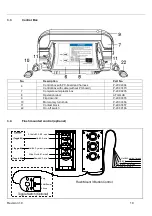
7.2.2.2
Control board plug setup ............................................... 28
7.2.3
Hydraulic Schematic ................................................................... 29
7.3
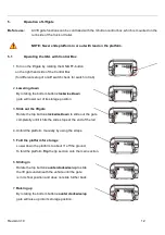
Functional Description of Hydraulics when Operating ............................... 30
7.3.1
Slide Out Function ...................................................................... 30
7.3.2
Lower Down ................................................................................ 30
7.3.3
Lift Up Function ........................................................................... 30
7.3.4
Slide In Function ......................................................................... 30
7.4
ILSL Push-Pull Valving ............................................................................. 31
8.
Needed Information for Ordering Spare Parts and Repairs .............................. 32
8.1
Ordering Spare Parts ................................................................................ 32
8.2
Repairs ..................................................................................................... 32
9.
Warranty ............................................................................................................... 33
10.
Contact Address .................................................................................................. 34
Table of Figures
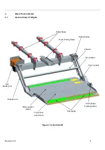
Figure 1: ILSL Slide lift
...................................................................................................... 8
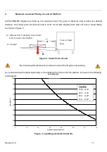
Figure 2: Center Point of Load ............................................................................................... 11
Figure 3: Load Diagram (ILSL 30 and 40) .............................................................................. 11
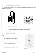
Figure 4: Hand Held Remote Control with Plug & Socket Wiring ........................................ 14
Figure 5: Lube Points 18
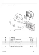
Figure 6: Power Pack (Side View) .......................................................................................... 19
Figure 7: Power Pack (Top View) ........................................................................................... 19
Figure 8: Main Wiring
.................................................................................................... 26
Figure 9: Hydraulic Schematic ............................................................................................... 29
List of Tables
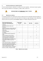
Table 1: Maintenance Schedule ............................................................................................. 15
Table 2: Recommended Hydraulic Fluids ............................................................................. 19
Table 3: Warranty Coverage Schedule .................................................................................. 33


