Larisch
08-502_99-04_00-03.doc
A22839,21.03.17
PALFINGER Tail Lifts GmbH
| Fockestraße 53 | D-
27777 Ganderkesee | T + 49 4221 853-0 | infombb@palfinger.com | www.palfinger.com
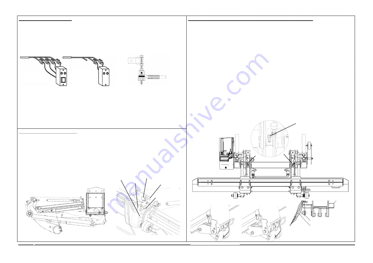
4. Installation of electrics
1.
Use the associated wiring diagram, which is located in the sealing cap on the right (in the direction of
driving), and observe the vehicle manufacturer's attachment guidelines.
2.
Feed battery cable to the battery, shorten if necessary and install cable lug.
3.
Install main fuse with cable lug and connect to the positive terminal of the battery.
4.
Lay the controller cable through to the driver's cab. In the driver's cabin select a place on the
instrument panel, establish electrical connections per wiring diagram and install control unit.
5.
If there is already a controller available in the vehicle then connect the loading tailgate in accordance
with the supplementary wiring diagram - request wiring diagram from
PALFINGER Tail Lifts
if
necessary.
6.
Connect the earth connection in accordance with the vehicle manufacturer's attachment guidelines.
7.
ATTENTION!
With hazardous goods vehicles, connect the earth cable to the battery or in
accordance with the respective vehicle manufacturer's attachment guidelines.
8.
Weld or fasten the control panel into place in accordance with the installation drawing.
9.
Note the following when attaching a manual cable switch.
Install the cable with terminal box
under the HGV loading area such that it is possible to make a connection from the cable there to the
manual cable switch. Connect the cable from the manual cable switch in the terminal box in
accordance with the wiring diagram. Find a suitable and secure storage location for the manual
cable switch.
10.
Operation of the manual cable switch only permissible from the marked position on the
platform.
6. Adjustment and installation work prior to commissioning
1.
Swing the platform into the HGV driving position and adjust the buffer stop such that the platform
lies on the buffer.
2.
Install the two other buffer stops on the installation depending on location, such that the platform
does not jump when the HGV is driving.
3.
Install switch b13 or b16 on the platform as shown.
4.
Remove the three connectors for the footswitch (not with basic) and Warnfix from the platform and
connect to the connectors coming from the control rod (yellow cable tie with yellow line, black with
black and the indicated cable ties with the designated connectors) and then insert the thus-
connected connectors back into the loading flap again and install the strain relief.
5.
Fasten the cable securely to the control rod with cable ties. Check for freedom of movement for the
platform and ensure appropriate cable lengths for this.
6.
All cables installed must be carefully laid and securely fastened. Sufficient bending lengths must be
observed.
7.
Drive the platform upwards and remove the transport securing screws on both mechanical joints.
8.
Lift, lower, fold in and fold out the platform several times in order to bleed the cylinder.
9.
Let the platform rest on the ground and lower the platform spikes. Adjust switch b13 or b16 as
shown and tighten the adjusting screw. Bring the platform to the HGV driving position and check
whether the warning lamps
extinguish with the control unit in switched off condition. Correct again if
required, fold back fuse panel.
10. Carry out oil level check with platform lowered, check all implemented screwed connections for tight
seating per installation drawing. Carry out acceptance test per test book and record in test book.
11.
Perform 125% overload test at load centre according to control booklet (page 9)
12.
Set platform tip 60mm above floor height by adjusting the platform clevis bolts.
5. Assembly of the platform
(mounted by PALFINGER Tail Lifts)
1.
Remove the oil tank plug screw and replace with the air filter provided.
2.
Let the lifting mechanism down via the side control panel until the platform can be mounted.
3.
With suitable lifting apparatus, bolt the platform to the torsion frame and parallel braces. Install the
torsion springs, swing the platform into horizontal position and lower it to the ground.
4.
Fold in platform spikes and platform and lean against the roller on the under-ride protection.
5.
Raise the platform far enough that the surface of the tunnel is horizontal.
6.
Now connect the parallel brace with the joint. Use the bolt, the spacer sleeve and the washer for this.
7.
Lower the platform until the bolt can be pushed through.
Caution, collision hazard
8.
Fasten bolt and install support roller.
9.
Slowly raise the platform until the stirrup bolt is loose and then remove this.
10. Gas pressure spring is now ready for operation.
Control unit for
motor vehicles
Control unit for
semi-trailers
and trailers
Main fuse
Strain relief and bracket
for b13 or b16
Connector for
footswitch and
Warnfix
Remove transport securing
screws
behind the lifting cylinders
Tunnel horizontal
Stirrup bolt
Joint
Bolt, spacer sleeve
Lever
Adjust b13
Align at 10°-15° to
tunnel
Adjust b16
Cable outlet to
platform
Platform clevis bolt


