background image

PTV 35/44/55/66                                                                                                                       Installation Manual 

Rev. 1.1


       71 


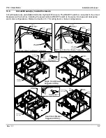
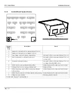
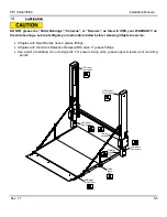
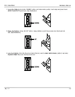
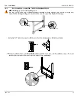
4. Raise the platform to bed level: Pu

shing the “UP” button, raise the platform to bed level. 


5. Bleeding the system: With the platform at bed level,  push the 

“UP” button for thirty (30) seconds.  This 

will  bypass  hydraulic  fluid  through  hydraulic  poppet  valves  located  in  each  of  the  lift  cylinder  pistons 
returning hydraulic fluid back to the reservoir via the return lines. 

UP


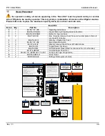
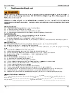
6. Closing and Storing of the Platform for transit: With the platform open at  bed level use the 

“UP” button 

and 

“CLOSE” button together, power the platform closed. 

UP

OPEN


Summary of Contents for PTV 44

Page 1: ...PTV INSTALLATION MANUAL PTV 33 3300 lbs Capacity PTV 44 4400 lbs Capacity PTV 55 5500 lbs Capacity PTV 66 6600 lbs Capacity 05 21 ...

Page 2: ...nge without notice Visit www palfinger com for up to date information and notifications If you received this product with damaged or missing parts contact Palfinger Liftgates at 888 774 5844 Parts Order liftgateparts palfinger com Technical Support technicalapplications palfinger com 15939 Piuma Ave Cerritos CA 90703 Tel 888 774 5844 Fax 562 924 8318 572 Whitehead Road Trenton NJ 08619 Tel 609 587...

Page 3: ...nsions Width Requirements 17 8 4 Strength Requirements 18 9 Body Preparation 19 9 1 Rear Bumper 19 9 2 Tow Hitch Auxiliary Equipment 20 9 3 Flush the Sill Sub Framing 21 9 4 Support Body 24 10 Liftgate Preparation 25 10 1 Liftgate Preparation 25 11 Liftgate Mounting 27 11 1 Mounting the Liftgate Standard Installation 27 11 2 Liftgate Welding 33 11 3 Bolt On Liftgate Installation Optional 37 11 3 1...

Page 4: ... Routing Wiring Crimping 56 13 6 Circuit Breaker at Enclosure 57 13 7 Battery Wiring Truck Kit 58 13 8 Battery Wiring Trailer Kit 59 13 9 Electrical Schematic 61 13 10 Control Board System Codes 62 13 11 Trailer to Tractor Ground Test 63 13 12 Tail Light Harness 64 14 Lubrication 65 15 Decal Placement 66 16 Cycle Test and Bleed the System 69 16 1 Cycle Test and Bleed the hydraulic system Standard ...

Page 5: ...visor Name Trailer Truck Year Make Model Liftgate Information Liftgate Serial Number Liftgate Model Number Date of Purchase Date of Installation 15939 Piuma Ave Cerritos CA 90703 Tel 888 774 5844 Fax 562 924 8318 572 Whitehead Road Trenton NJ 08619 Tel 609 587 4200 Fax 609 587 4201 ...

Page 6: ...PTV 33 44 55 66 Installation Manual Rev 1 1 4 1 Manual Updates Revision Description v1 0 Initial Release ...

Page 7: ...ult in death or serious injury WARNING indicates potentially hazardous situation which if not avoided could result in death or serious injury CAUTION indicates a potentially hazardous situation which if not avoided may result minor or moderate injury CAUTION without the safety alert symbol is used to address practices not related to personal injury In this manual we use it to alert you to potentia...

Page 8: ...tions before adding any auxiliary equipment The installer is responsible for compliance with this manual OEM and FMVSS requirements The installer should never place any portion of him herself or any other person underneath the liftgate at any point during the installation unless the liftgate is fully welded AND all moving components are safely secured All welding should be performed by qualified p...

Page 9: ... only the PTV series liftgate which is designed for different capacities There are four options available to determine the model and serial number of the installed liftgate 1 Refer to the serial number tag on the liftgate Located on Left Side Column as shown below Cerritos CA Trenton N J 888 774 5844 Model Serial No Date ILD ML680 VL A 0123456789 OR Serial Number Location 2 Ask your employer or le...

Page 10: ...ti Meter Snap Ring Pliers Hammer SAE Metric Allen key Set Impact Sockets SAE Metric Socket Set Assorted Drill Bits Floor Jack or Equivalent Sm To Med Bottle Jack Forklift or Overhead Hoist Handheld Grinder Paint Gun Accessories Pry Bar 3 8 Drill Motor Grease Gun Heat Gun or Equivalent Min 250A Welder Cutting Torch or Equivalent Framing Square Measuring Tape ...

Page 11: ...onents Single Pump KET06882A Cable 11 3 8 Lugs 2GA Red 1 pc KET06062A Bus Bar Red 2 pcs KET05916A Bus Bar Black 2 pcs EM 781 Nut Serrated 3 8 16 SS 6 pcs Electric Components Dual Pump KET06882A Cable 11 3 8 Lugs 2GA Red 2 pc KET06062A Bus Bar Red 2 pcs KET05916A Bus Bar Black 2 pcs EM 781 Nut Serrated 3 8 16 SS 6 pcs Hydraulic Fittings Kit 80 1121 100 Elbow 90 1 4 JIC Female 1 4 JIC Male 2 pcs Elb...

Page 12: ...upport Chains Right Side Column Traverse Main Control Switch Load Center Left Side Runner Right Side Runner Aluminum Retention Ramp Fixed Ramp Fixed Ramp w Cart Stops Ramp options shown below are steel platform ramps Same options are available for aluminum platforms Platform Tip Section Platform Main Section Toggle Switch Not Shown ...

Page 13: ...reakers Auxiliary Remote Control Cable Entry Ports Hydraulic Enclosure Dual Pump Configuration Hydraulic Enclosure Single Pump Configuration Secondary Pump Motor Control Board Primary Pump Motor Battery Compartment Master Shutoff Switch Shipping Brace Enclosure Cover Carrier Frame Battery Voltage Gauge Manual Reset Circuit Breaker Auxiliary Remote Control Cable Entry Ports Security Lock Hole Secur...

Page 14: ...e ________ L Frame Height Height of chassis frame ________ Truck Information Truck Dimensions Type of Body check applicable Van Flatbed Reefer Other specify ____________ Type of Rear Door check applicable Flip Up Roll Up Swing Other specify ________________ Truck Specifications Manufacturer ex Hino GVWR ex 68 000 lbs Length ex 53ft Width 96 102 Truck Chassis Dimension Sheet Liftgates Information M...

Page 15: ...f the trailer slider holes ________ X Eyebrow depth ________ Z Top of floor where the liftgate platform will meet the top of the eyebrow ________ Customer Information Quote SO ____________________________________________________ Company ______________________________________________________ Phone _________________________________________________________ Email _________________________ ____________...

Page 16: ...cannot be installed with barn or full opening swing door types Trucks need to be 26 000 lbs GVWR Gross Vehicle Weight Rating and above It is not recommended to cut torch or remove the support materials from the rear sill of the truck or trailer Installers are advised to use a sub frame or flush sills as required Removing gussets stiffeners light rings or other such support structures may VOID your...

Page 17: ...t your gate is compatible with your vehicles bed height Liftgate Model Platform Depth Platform Width Based on Vehicle Width Dock Loading Bed Height Range NO Dock Loading Bed Height Range 96 W 102 W Min Max Min Max PTV BG 42 16 ARR 80 86 46 56 34 56 PTV 60 12 Fixed Ramp 80 86 32 56 34 56 PTV 60 16 ARR 80 86 32 56 34 56 PTV 72 12 Fixed Ramp 80 86 38 56 34 56 PTV 72 16 ARR 80 86 38 56 34 56 PTV 84 16...

Page 18: ...hat your gate is compatible with your vehicles bed height Liftgate Model Platform Depth Platform Width Based on Vehicle Width Dock Loading Bed Height Range NO Dock Loading Bed Height Range 96 W 102 W Min Max Min Max PTV BG 42 16 ARR 80 86 46 56 34 56 PTV 60 12 Fixed Ramp 80 86 32 56 34 56 PTV 60 16 ARR 80 86 32 56 34 56 PTV 72 12 Fixed Ramp 80 86 38 56 34 56 PTV 72 16 ARR 80 86 38 56 34 56 PTV 84 ...

Page 19: ...r Width Outside Column Dim Inside Column Dim Inside Platform Chain Plate Overall Outside Dim Overall Liftgate Dim H xW 96 Wide Body 94 7 16 84 3 8 78 5 8 95 7 16 90 5 16 x 95 7 16 94 7 16 78 5 8 95 7 16 90 5 16 75 3 16 74 9 16 84 3 8 15 1 8 Nominal Truck or Trailer Width Outside Column Dim Inside Column Dim Inside Platform Chain Plate Overall Outside Dim Overall Liftgate Dim H xW 102 Wide Body 100...

Page 20: ... post and rear sill strength requirements are met for your liftgate Truck body or trailer must be capable of supporting minimum forces and loads shown below Side Wall Requirements PTV 35 PTV 44 PTV 55 PTV 66 X Side Wall Tension 1900 lbs 2400 lbs 2950 lbs 3500 lbs Y Side Wall Compression 1900 lbs 2400 lbs 2950 lbs 3500 lbs Z Side Wall Shear 2700 lbs 3100 lbs 3800 lbs 4300 lbs ...

Page 21: ...urface for the liftgate It is not recommended to cut torch or remove the support materials from the rear sill of the truck or trailer Installers are advised to sub frame or flush sills as required Removing gussets stiffeners light rings or other such support structures may VOID your truck body or trailer warranty 2 Remove Rear Protrusions Be certain that the under ride bumper trailer hitch or othe...

Page 22: ... they must not stick out further than the rear sill Relocate or remove tow hitch or other auxiliary equipment if necessary Fig 3 If the tow hitch or other auxiliary equipment must be removed or adjusted ensure that work is done by a qualified professional Removing or relocating tow hitches or other equipment may void the warranty Bed Level Rear Sill Hitch or other Equipment must NOT extend rearwar...

Page 23: ...3 16 or greater wall tubing before liftgate is mounted Or the liftgate can be mounted into position and the sub frame can be built as the liftgate is installed with 3 16 or greater flat bar Fig 5 In either case the liftgate installation weld procedure does not change These examples are show below Flushing the floor or filling the gap between the sill and liftgate can span up to 6 without cross sup...

Page 24: ...PTV 35 44 55 66 Installation Manual Rev 1 1 22 Tubing Subframe Flat Bar Subframe 2 pcs per Column Liftgate Column Liftgate Column Vehicle Corner Post Vehicle Corner Post Fig 5 ...

Page 25: ...ould NOT be removed It is recommended to use flat bar with the same thickness as the stiffeners typically to 3 8 thick x 3 wide The liftgate Installation weld procedure is the same Corner Stiffener Corner Stiffener Flat Bar Flat Bar Flat Bar Flat Even Surface after installing flatbar Stiffener Flatbar Thickness ...

Page 26: ...a support is required add support bars as shown below Flatbed installations may use a similar arrangement with 3 16 x 4 x 4 min rectangular tubing for corner posts and 3 channels for support bars 72 Approximately 60 Support Bar 1 4 x3 Min Flat Bar 1 4 x3 weld each end Sub plate for aluminum side rails 1 4 x4 min bolted on either side of the body cross members ...

Page 27: ...ove Shipping Bands Remove bands Cut the bands from the front and rear of the liftgate and the rear The hat section s are banded to the column cut the bands to remove hat sections The light and control wire harness are bagged for protection cut the bands and leave the harnesses in the bag until ready to install Rear Light Wire Harness Bagged Rear Light Wire Harness and Operational Remote Harness Ba...

Page 28: ...ate Ready for Installation After removal of the shipping bands and the hydraulic enclosure the liftgate is ready for installation as shown below DO NOT remove any braces before or during installation until instructed to do so Horizontal Top Brace Horizontal Bottom Brace Shipping Stand Shipping Stand Bagged Wire Harnesses Bagged Wire Harnesses If the body of the truck is narrower than the inside of...

Page 29: ...Mounting the Liftgate Standard Installation Before positioning the liftgate consider when measuring and centering the liftgate that the truck or trailer may NOT be perpendicular to the ground Special care must be taken to ensure that the liftgate is perpendicular to the ground before welding Steps 1 Level Vehicle The vehicle must be on level and even ground Uneven ground will give misleading measu...

Page 30: ... the top of the liftgate tight against the body for welding Liftgate Column Forklift Forks Horizontal Top Brace 4 x4 x24 Woodstock Clamp 3 Remove Shipping Stand Hoist the liftgate approximately 8 off the ground and remove the two 2 bolts located on the outside of the shipping stand for the street and curb side columns After removing the shipping stands install two 2 20x1 bolts on each column torqu...

Page 31: ...y the lifting device and not the alignment plates Fig 7 Do not remove the lifting device 4 Fit Liftgate Against Truck Use a forklift recommended to position the liftgate flush against the vehicles corner posts and sill Liftgate Column Liftgate Alignment Plate Liftgate Traverse Street Side Column Side View Flush Corner Post with Liftgate Columns Vehicle Floor Vehicle Rear Sill Fig 7 ...

Page 32: ...edges of the columns to the edges of the vehicle using a measuring tape Measure at the top of the columns and the at bottom both measurements must be the same Fig 8 If both sides don t measure equally shift the liftgate as required Measuring Tape Vehicle Corner Post Liftgate Column Distance must be equal at top and bottom of column Curb Side Street Side Fig 8 ...

Page 33: ...mns are square and parallel Use a framing square to verify columns are square at 90 to the vehicle s sill and body Measurements should reflect dimensions below when measured from the indicated points 120 120 84 9 16 124 1 2 124 1 2 90 9 16 94 7 16 100 7 16 Cylinder Mount Plate Nylon Bumper Liftgate Column ...

Page 34: ...m all mounting dimensions are correct check to ensure that the floor and traverse are flush and that the columns are flush to the vehicle F Style Clamps F Style Clamp Vehicle Corner Post Liftgate Column DO NOT begin welding until dimensions are checked liftgate is squared clamped tightly and rechecked after each positioning adjustment Do not remove lifting device forklift crane other until instruc...

Page 35: ...an be added in the corner to minimize pull from welding Fig 10 Round Stock Vehicle Corner Post Vehicle Corner Post with Radius Bumper Plate Bumper Plate Vehicle Corner Post Dock Bumper Top View Left Side Column with Flatbar Top View Left Side Column with Round Stock Column Column Flatbar Vehicle Corner Post with Radius Bumper Plate Dock Bumper Column Vehicle Corner Post Steps Fig 10 ...

Page 36: ...elds Weld inside of columns from top to bottom Curb side column shown below repeat welding procedure on street side column 3 Traverse Welds Weld traverse per vehicle width 96 W or 102 W as shown below Do not weld the alignment plates 1 4 2 18 2X 1 4 2 22 96 W 102 W 1 4 2 20 Inside Column Welds Traverse Welds ...

Page 37: ... a weld on the dock bumpers as shown and x 3 welds 5 places evenly spaced on columns top to bottom Do not weld near the control area Fig 11 Repeat welding procedure on the street side column DO NOT WELD AREA 1 4 3 2X 5 Remove Alignment Plates Remove the bolts securing the alignment plates on the left and right side Fig 11 ...

Page 38: ...e forklift Second remove the clamps and finally remove the liftgate braces Remove all clamping devices Unbolt Top Brace 4X Remove Top Brace Remove all clamping devices Remove Bottom Brace Remove Forklift 7 Gate Mounting Complete Standard lifegate mounting is now complete proceed to hydraulic installation ...

Page 39: ...stalled Method 1 Factory Installed The liftgate arrives from the factory with the Vehicle Brackets installed on the liftgate Vehicles Brackets will be secured to the liftgate columns at the top and bottom with bolts Liftgate Bridge Right Side Vehicle Bracket Left Side Vehicle Bracket Bolt On Column Wrap Bolt Securing Vehicle Bracket to Liftgate Colum Nut bar Securing Column Wrap to Vehicle Bracket...

Page 40: ...ng and Welding procedures from Sections 10 11 3 Finalizing Installation To finalize this method of installation both column wraps on the liftgate must be welded to the vehicle in the location shown below Right Bolt On Column Wrap Vehicle Corner Post 1 4 3 2X Optional For moderate to heavy use it is recommended to weld the column wraps to the vehicle End of Vehicle Body 3 1 4 2X ...

Page 41: ...olt On Subframe Vehicle Bracket and Bridge Liftgate Columns w Alignment Buttons Vehicle Bracket Button Slots Alignment Buttons on Liftgate Columns Liftgate Traverse Liftgate Alignment Plate Vehicle Rear Sill Vehicle Bracket Bridge Bolts 4X 9 16 12 X 1 3 4 Torque 108 ft lbs 2X 2 20 Welding for 96 Wide Vehicle 1 4 2 22 Welding for 102 Wide Vehicle Vehicle Bracket Assembly with Vehicle Bracket Bridge...

Page 42: ...gate columns become flush with the Vehicle Brackets Slowly lower the forklift forks hoist so that all buttons are seated properly in the vehicle bracket slots Alignment Buttons on Front Surface of Columns Vehicle Bracket Button Slots 3 Bolting the Columns Use the provided bolts to prevent the column buttons from moving out location on the vehicle bracket Install two bolts on the right and left sid...

Page 43: ...l secure the top section of the column to the vehicle bracket After installing the bolt reinstall the column caps back to the column using the same hardware Torque 5 8 bolts to 204 ft lbs Column Cap Bolt 5 8 18 x 1 3 4 Torque 204 ft lbs Vehicle Corner Post Vehicle Bracket Liftgate Top Brace LiftgateTop Brace Hardware Torque to 25 ft lb Nylock Nut Clamp Washer ...

Page 44: ...d in the wheelbase and forward of the rear wheels when permitted B Relocation Hose Kit 1 C Relocation Hose Kit 2 D Relocation Hose Kit 3 Side View Right Side A Standard Hose Kit Shipped Standard w liftgate Side View Right Side Hose Kit Part No Relocation Kit Hose Kit Length Application Recommended A 80 1121 001 Included with Liftgate 3 ft 36 914mm Pump Battery box mounted behind rear wheels B 80 1...

Page 45: ...sure Weld the enclosure to body cross members with x 1 1 4 welds Weld to a minimum of four 4 crossmembers Weld front rear and sides of angles at each crossmember Observe the recommended welding practices shown below Fig 12 Vehicle Front View Crossmember Floor 1 4 1 1 4 8X 8X Hydraulic Enclosure 8X 1 4 1 1 1 4 1 4 Vehicle Front View Crossmember Floor 1 4 1 1 4 8X 8X Hydraulic Enclosure 8X 1 4 1 36 ...

Page 46: ... reinstall the four nuts on the enclosure Remove Four Nuts Only Shipping Braces 12 4 Hydraulic Connections To open the lid of the box remove the security bolt below the lid handle Pump and Motor fittings are located on the left side of the enclosure Secondary pump is optional 3 ft Hose Kit Included with Liftgate 3 8 Hoses 3 FT 36 1 4 Hoses 3 FT 36 Secondary Pump Optional ...

Page 47: ...mber Secure with thread cutting flange screws Hydraulic Enclosure Security Bolt Bottom View of Vehicle Curb Side Column Hat Section Hydraulic Enclosure Drill Holes Through Hat Section and Crossmember Front of Vehicle Rear of Vehicle Curb Side Column Tires DO NOT weld hat section with hydraulic hoses or electrical wires installed Hat Section Welded Position the hat section as described in the bolt ...

Page 48: ...rness can be found Position hoses opposite to each other 3 8 hoses should have one male and one female exposed at each end Position the hoses in the same manner one male and one female at each end Fig 13 Route the control wire harness and the all hoses through the hat section s and out towards the hydraulic enclosure 3 8 Male 3 8 Female 1 4 Female 1 4 Male J30 Control Harness Curb Side Column Cont...

Page 49: ...cannot be installed due to the construction of the vehicle connect the male and female hoses going to the hydraulic enclosure directly to the hydraulic junction block Fig 15 1 4 90 Elbow 3 8 90 Elbow 3 8 90 Elbow 1 4 90 Elbow Hydraulic Block Front View of Right Column Hydraulic Block 1 4 Male End Hose 1 4 Female End Hose 3 8 Female End Hose 3 8 Male End Hose Order of Installation for Hydraulic Fit...

Page 50: ...ulic Enclosure Remove the plugs and caps Fig 16 from the side of the hydraulic pump and motor enclosure Hat Section Hoses from Column Caps Plug Plug Route the hoses coming from the column over to the hydraulic enclosure Fig 17 Route along the enclosure frame When routing hoses never make sharp bends maintain a natural hose radius Connect the hoses from the hydraulic block to the pump motor hydraul...

Page 51: ...r Side of Hydraulic Enclosure Screw Lock Nut Volt Meter On the inside of the Hydraulic Enclosure open the control board cover by pulling the side of the rubber cover out of the locking tab Unhook the two flex straps that secure the control board to the rubber cover Plug the control harness connector into the J30 port of the control board Power LED Control Box Location Flex Strap Rubber Cover Locki...

Page 52: ...ved Fig 21 At the hydraulic enclosure entry cut one grommet as shown in Fig 19 and fit the cut grommet over the J11 harness Position the J11 harness with grommet in one of the grommet slots on the cover and screw the cover back on to the enclosure Voltmeter Side of Hydraulic Enclosure Cut Grommet Cut Fit Cut Grommet Over the Harness Cover Plate Screw Lock Nut Control Box Location Control Board Rou...

Page 53: ... hole pattern below and mount the switch with the provided screws Fig 22 Wire the switch and harness per diagram Test the switch After testing and making sure the switch is functioning properly place the decal near the switch Fig 23 ø 11 16 2X ø 1 8 No Use Blue 4 Black Black Yellow Green Yellow Green 2 4 1 Red 2 J11 Black Blue 3 White 1 J11 From Control Board Decal Cab Shutoff Switch Mounting Hole...

Page 54: ...a Ave Cerritos CA 90703 M 207 BAR 3000 PSI A B 69 BAR 1000 PSI C D 1 72 CC REV 0 105 IN REV T1 P1 M 1 72 CC REV 0 105 IN REV S1 S2 S5 S4 S3 M S1 LIFT M S2 S5 POWER DOWN S5 GRAVITY DOWN M S4 TILT OPEN M S3 TILT CLOSE LIFT CYLINDER 1 LIFT CYLINDER 2 OPEN CLOSE CYLINDER SECONDARY PUMP UNIT OPTIONAL PRIMARY PUMP UNIT RESERVOIR 2 6 GPM ...

Page 55: ...d Installed from Factory Property HYDREX MV ARCTIC 15 Start Up Temperature 50 C 58 F Operating Temperature 45 C to 23 C 49 F to 73 F Pour Point 57 C 71 F Flash Point 128 C 262 F Density 15 C 59 F kg L 0 834 Viscosity cSt 40 C SUV 100 F cSt 100 C SUV 210 F cP 50 C 58 F 13 0 69 7 4 95 42 5 1 310 When changing fluids it is highly recommended to use Hydrex MV Arctic 15 fluid however alternatives fluid...

Page 56: ...braided hoses and other vehicle components Never exceed rating of existing fuses located at the battery control board and or the pump and motor which may result in serious damage to the equipment Never jump the 175 Amp circuit breaker at the batteries unless otherwise instructed by the Palfinger Liftgates technical support group Assure all connections are tight and securely sealed Heat shrink all ...

Page 57: ... enclosure with positive terminals to the right side as shown Secure the batteries to the box with the battery strap kit 3 Battery Strap Kit and Buss Bars Secure the batteries to the enclosure with the battery strap kit provided The nylon strap is made for a 3 battery setup When installing only 2 batteries the nylon strap will require trimming as shown Connect the three 3 batteries in parallel by ...

Page 58: ...the wire along the wooded spacer with insulated cable clamps Body Long Sill Wooden Spacer s Chassis Frame U Bolt Cable Routed Outside of U Bolts w Slack Insulated Cable Clamps Cable Routed on Inside of Channel All grounding surfaces MUST be cleaned prepped and sealed per this manual Cut to size cables MUST be properly crimped and sealed as factory supplied All connections MUST be dressed with diel...

Page 59: ...reakers Circuit Breaker Primary Pump Motor Power Cable Dual Pump Motor Circuit Breaker Configuration Single Pump Motor Circuit Breaker Configuration Power Cable To Batteries Power Cables To Batteries ON OFF Switch ON OFF Switch Dual Circuit Breaker Suggested Wiring Circuit Breaker Power Cable Jumper Ground Cable From Motor Ground Cable From Vehicle Power Cable Jumper Power Cable Jumpers Power Cabl...

Page 60: ...Kit Single Pump Aux Battery 40 ft 36 11 74 Circuit Breaker Flag Reset Positive Ground Charging Circuit Breaker Auto Reset Starter Solenoid 2 Motor 2 Motor 1 Auxiliary Batteries Master Shut Off Switch Ground to Chassis Ground to Chassis Truck Batteries 12V Truck Kit Dual Pump Aux Battery 40 ft 36 11 74 11 36 Circuit Breaker Flag Reset Positive Ground 40 ft 40 ft 42 Motor Circuit Breakers Flag Reset...

Page 61: ...e Pump Single Pole Aux Battery 40 ft 36 11 74 Charging Circuit Breaker Auto Reset Starter Solenoid Motor 1 Auxiliary Batteries Ground to Trailer Side Rail Master Shut Off Switch 12V Trailer Kit Single Pump Dual Pole Aux Battery 36 11 74 40 FT Trailer Socket Single Pole Trailer Socket Dual Pole Positive Ground Positive Ground Auxiliary Batteries 42 Motor Circuit Breakers Flag Reset 11 42 Motor Circ...

Page 62: ...ry Trailer Socket Single Pole 40 ft 36 11 74 11 36 Positive Ground Charging Circuit Breaker Auto Reset Starter Solenoid 2 Starter Solenoid 1 Motor 2 Motor 1 12v Battery Ground to Trailer Side Rail Master Shut Off Switch 12V Trailer Kit Dual Pump Dual Pole Aux Battery Trailer Socket Dual Pole Motor Circuit Breakers Flag Reset 36 11 11 36 74 42 42 11 42 42 Motor Circuit Breakers Flag Reset 40 Ft 40 ...

Page 63: ...CA 90703 70 1121 001_a PTV Electrical Schematic Power LED Volt Gauge Ground to Chassis Master Shut Off Switch Pump and Electric Motors 15 A Fuse 15 A Fuse Cab Shutoff Switch Optional Valves Power Source Auxiliary Hand Control Column Toggle Switch External Control Switch Yl gn 3 1 2 2 1 3 Yl gn BU BN ...

Page 64: ...n or disconnect bridge J11 2 4 or close tail lift 8 General short in electric wiring Cab switch off on or disconnect bridge J11 2 4 or voltage interruption MBB control 9 Defect at motor solenoid detected during lifting Automatically when the valves are back to normal A Voltage V02 J1 pin 2 is missing defective fuse Replace the fuse b Defect at opening valve S3 S4 or motor relay detected during ope...

Page 65: ...on tractor including ground 2 Trailer Test Ground battery load tester on trailer chassis point C Connect positive cable on positive pole of single pole plug receptacle on trailer B Run load test This will test entire circuit on tractor including circuit breakers and ground between trailer batteries and trailer chassis 3 Tractor and Trailer Charging system test while connected Ground battery load t...

Page 66: ... light harness to avoid any of the sharp edges on the liftgate columns Tail Light Adapter Harness Palfinger Liftgates will provide harness adapters that will are plug and play and compatible with different type of tailer tail light harnesses A Connector type must be specified during the ordering process to receive the correct adapter harness ATTENTION Routing Light Harness Never route the light ha...

Page 67: ...sing liftgate to service Liftgates with Fixed Ramps have 9 grease fittings Liftgates with Aluminum Retention Ramps ARR have 11 grease fittings Use a light penetrating oil on closing aids For power closing units grease upper lower pivot mounting points ARR Hinge Both Sides Chain Arms Pins Platform Hinge Pins Lift Cylinder Pins Lower Lift Cylinder Pins Upper Closing Cylinder Lift Cylinder Pins Lower...

Page 68: ...use this lift gate for anything but it s intended use The lift gate is not equipped with a back up system to prevent falling in the event of a failure BEFORE OPERATING LIFT BE SURE YOU UNDERSTAND OPEN AND CLOSE LIFTGATE WITH PLATFORM FULLY RAISED 1 Power liftgate by turning the master disconnect switch to the ON position Switch is located on the pump box 2 Be certain operating area around platform...

Page 69: ...PTV 35 44 55 66 Installation Manual Rev 1 1 67 G A K C F D B H E G E D J N N M M ...

Page 70: ...ommended that the installer refer to the Code of Federal Regulations CFR which can be viewed at http ECFR gpoaccess gov H Dimension 15 H 60 from ground to center of tape Requirement 3 Red white reflective tape applied across the entire width of the rear underride protection device Note Not required if no underride protection is equipped Requirement 2 On each corner Two 12 long white reflective pie...

Page 71: ...is will confirm all controls work correctly and hydraulic system is completely bled of air 16 2 Operating Instructions Standard Units Steps 1 Turn on power To activate power to the liftgate turn the master disconnect switch located on the outside of the battery box to the ON position If the vehicle has a cab switch verify that its turned ON also Cab Shutoff Switch OFF ON ON OFF Switch on Outside o...

Page 72: ...ea around platform is clear before opening platform Pushing the DOWN button and OPEN button together to power the platform open OPEN DOWN 3 Lower the platform to the ground Pushing the DOWN button lower the platform to the ground Note for power down operation push the down button twice within 3 seconds DOWN ...

Page 73: ...l push the UP button for thirty 30 seconds This will bypass hydraulic fluid through hydraulic poppet valves located in each of the lift cylinder pistons returning hydraulic fluid back to the reservoir via the return lines UP 6 Closing and Storing of the Platform for transit With the platform open at bed level use the UP button and CLOSE button together power the platform closed UP OPEN ...

Page 74: ... down platform past the Travel Locks See Illustration DOWN 8 Raise the Platform Using the UP button raise platform up until travel ears clear the travel lock slot See Illustration UP 9 Lock the Platform Once the travel ear clears the slot use the down button twice within 3 seconds to power down travel ear into travel lock slot DOWN ...

Page 75: ...to liftgate components Be sure to inspect the liftgate for damage Front View of Liftgate Dock Stops on Traverse Hooks on Side of Platform Sidebar 1 Using the UP button to power platform up so that it is completely out of the travel locks UP 2 To lower platform down push Down Button twice within 3 seconds until the platform passes the travel latch and is level with the vehicle floor and rests on th...

Page 76: ...ines are secured with cable ties clamps or other fasteners and are away from sharp edges and moving parts Circuit Breakers installed and wired per instructions Lights wired properly and operate per DOT State and Federal requirements Load test has been performed as explained in Section 13 11 Trailer to Tractor Ground Test Measure battery voltages Flooded Batteries 12 6V AGM Batteries 12 8V Operatio...

Page 77: ...PTV 35 44 55 66 Installation Manual Rev 1 1 75 ...

Reviews:

Related manuals for PTV 44