background image

Chapter 3 General

13

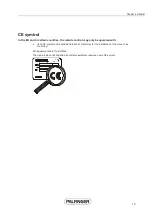
CE symbol

In the EU and in certain countries, the remote control may only be operated with:

x

Valid CE symbol and a valid declaration of conformity for the installation of the crane to be 
controlled.

EU requirements are thus fulfilled.

The crane to be controlled and all ancillary equipment require an own CE symbol.

Summary of Contents for RC 400 P2

Page 1: ......

Page 2: ......

Page 3: ...ectively over the long term x Please follow all safety instructions x Please maintain your PALFINGER unit in accordance with regulations x Please adhere to the prescribed maintenance intervals x The u...

Page 4: ......

Page 5: ...e 26 Feedback signal at the handset 26 Support operation linear lever 27 Linear lever for front mounting 8x 27 Linear lever for rear mounting 8x 27 Linear lever for front rear mounting 4x 28 Support o...

Page 6: ...Contents...

Page 7: ...er 1 1 In this chapter Operating instructions 3 Validity of operating instructions 3 Operating company 4 Terms 4 Symbols 5 Sketches and pictures 5 C H A P T E R 1 Notes regarding the operating instruc...

Page 8: ......

Page 9: ...FINGER is anxious to apply the latest and most advanced technology in their devices by further development This may result in deviations between operating instructions and the actual unit Please conta...

Page 10: ...th the crane Authorised Authorised by PALFINGER service workshops through tests a corresponding driver s license operator training on the crane etc Properly A person who observes and complies with all...

Page 11: ...n death or serious injury for operator and others Warning These symbols and the Warning signal word are used for immediately threatening dangers Ignoring this instruction could result in death or seri...

Page 12: ......

Page 13: ...Chapter 2 7 In this chapter General 9 Crane control systems 9 Components of the remote control 9 Guidelines to prevent dangers 9 C H A P T E R 2 Safety and Health Standards...

Page 14: ......

Page 15: ...become obvious Components of the remote control Only original PALFINGER components must be used to operate the remote control system Guidelines to prevent dangers x In the event of danger operate the...

Page 16: ......

Page 17: ...Chapter 3 11 In this chapter CE symbol 13 C H A P T E R 3 General...

Page 18: ......

Page 19: ...the remote control may only be operated with x Valid CE symbol and a valid declaration of conformity for the installation of the crane to be controlled EU requirements are thus fulfilled The crane to...

Page 20: ......

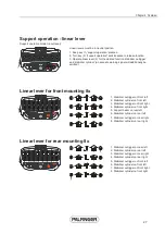
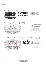
Page 21: ...on damping 24 Remote control safety shutdown 25 Storage 26 Feedback signal at the handset 26 Support operation linear lever 27 Linear lever for front mounting 8x 27 Linear lever for rear mounting 8x 2...

Page 22: ......

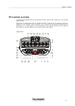
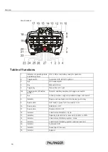
Page 23: ...an example and shows the standard functions If requested by the customer the function assignment of the switches levers or displays can be changed by authorised PALFINGER service workshops Prior to in...

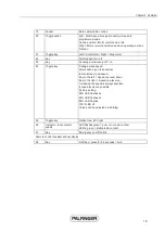
Page 24: ...witch 7 Key Crane operation support operation change over switch 8 Indicator Rope winch overload protection device push stop 9 Push button OLP button press for 0 5 seconds horn 10 Push button EHPLS On...

Page 25: ...e speed After switching on the handset last selected crane speed Key to the left Speed one level down Key to the right Speed one level up Increasing the speed is always possible 4 speed levels are pos...

Page 26: ...ction assignment can be changed by any authorised PALFINGER service workshop The assignment is shown by adhesive labels on every remote control Stabilizer outrigger operator side Extend Retract Stabil...

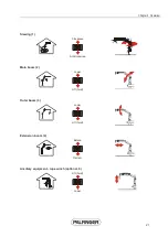
Page 27: ...pter 4 Overview 21 Slewing 1 Clockwise Anticlockwise Main boom 2 Lower Lift hoist Outer boom 3 Lower Lift hoist Extension boom 4 Extend Retract Ancillary equipment rope winch optional 8 Lift hoist Low...

Page 28: ...equipment grab optional 7 Open Close Ancillary equipment rotator optional 8 Clockwise Anticlockwise Ancillary equipment fly jib lower optional 5 Lower Lift hoist Ancillary equipment fly jib extend opt...

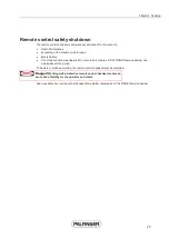
Page 29: ...utton The emergency cut off button stops all crane functions within 0 5 seconds 500 ms after activation in an emergency situation An emergency cut off button can be found at every operating station an...

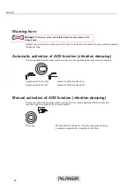
Page 30: ...function prevents the outer boom from oscillating after jerky crane movements Toggle wwitch to the right Automatic AOS is switched on Toggle switch to the left Automatic AOS is switched off Manual act...

Page 31: ...If no crane function was operated for more than 5 minutes A PALFINGER service partner can individually set the period To be able to continue working the remote control handset must be restarted Danger...

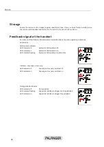
Page 32: ...tructions Additionally AOS function indicator LED indicator off LED indicator on LED indicator flashing Automatic AOS switched off Automatic AOS switched on Automatic AOS switched on and active Indica...

Page 33: ...80 100 1 2 3 4 5 6 7 8 1 Stabilizer outrigger on front left 2 Stabilizer cylinder on front left 3 Stabilizer outrigger on front right 4 Stabilizer cylinder on front right 5 Support beam on rear left...

Page 34: ...eft for confirmation to release the function 3 Operate joystick for the desired function stabilizer outrigger and stabilizer cylinder an acoustic warning signal will additionally be emitted Joystick f...

Page 35: ...ts When the poles connect a short circuit occurs x For the protection of other people store the battery and replacement battery safely x Do not use batteries that are not allowed for this remote contr...

Page 36: ...r red and green lights on where it remains fully charged trickle charging If the charger is off the battery will lose its full capacity Disposal EU countries Dispose defective or used up batteries acc...

Page 37: ...Chapter 5 31 In this chapter Preparing for remote operation 33 Functional check 33 C H A P T E R 5 Preparing for remote operation...

Page 38: ......

Page 39: ...re using the remote control Battery Operating time with a charged battery is approx 8h Always handle batteries with care Carry the charged spare battery with you in the vehicle Carry the cable with yo...

Page 40: ......

Page 41: ...ransport position of the rope winch 38 Changing the radio channel in the event of a radio interference 38 Cable operation 38 Attaching and detaching of loads by the crane operator 39 Interrupting the...

Page 42: ......

Page 43: ...lever in neutral position x Release the emergency cut off button on the remote control handset x Press the start key 3 on the remote control handset The remote control is ready for operation The vehic...

Page 44: ...oustic signal Changing the radio channel in the event of a radio interference Briefly press key 3 2x If change of channel has been successful this is indicated by an acoustic signal 12 channel frequen...

Page 45: ...he load to the load lug x Exit the working area x Release the emergency cut off button x Crane movements are once again permitted Detaching of load by the operator x Lift the load to the respective po...

Page 46: ......

Page 47: ...Chapter 7 41 In this chapter Maintenance and care 43 Repairs 43 Disposal 43 C H A P T E R 7 Maintenance...

Page 48: ......

Page 49: ...buttons levers immediately x check also the remote control handset for proper operation every time servicing is carried out Repairs x Damages to the unit must be repaired immediately by a PALFINGER pa...

Page 50: ......
Page 51: ...l supports 29 Joystick for front rear mounting without additional support 28 L Linear lever for front mounting 8x 27 Linear lever for front rear mounting 4x 28 Linear lever for rear mounting 8x 27 M M...

Page 52: ...Index 46 T Table of functions 18 Terms 4 V Validity of operating instructions 3 W Warning horn 24 Working or transport position of the rope winch 38...

Reviews: