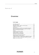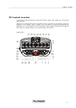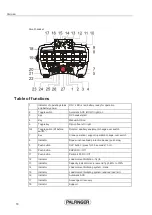
Chapter 4 Overview
29
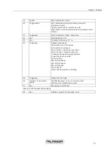
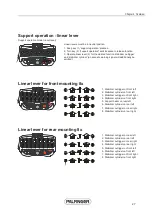
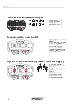
Joystick for front/rear mounting (with additional supports)
With additional supports
1.) Keep 'support operation' key 1
pressed.
2.) Lift up lift-before-switch and shift
right (mode for additional supports),
shift left (mode for crane supports).
3.) Additional left stabilizer
outrigger
4.) Additional left stabilizer cylinder
5.) Additional right stabilizer
outrigger
6.) Additional right stabilizer
cylinder
Battery of the remote control
Use the handset only with the original batteries.
Information!
A new battery is not yet fully charged when delivered!
First read the safety guidelines, then the charging instructions. The
battery will reach its full capacity only after having completed the first
three to five charging / discharging cycles.
Safety instructions:
x
Insert the battery in the handset correctly (positive and negative pole).
x
Never leave the battery near fire.
x
Never leave the battery near metal or live parts. When the poles connect a short circuit occurs.
x
For the protection of other people store the battery and replacement battery safely.
x
Do not use batteries that are not allowed for this remote control handset.
x
Use original batteries only in devices approved by the manufacturer.
x
Protect battery, charger and handset against moisture and dirt.
Danger!
If handled improperly, batteries may leak, burst open, burn
or even explode! There is an acute danger of accident!
Charging procedure:
x
Leave the battery in the handset of the RC system until an acoustic interval signal indicates that
the battery needs charging.
x
Insert the battery in the battery compartment of the charger. LED (charging) on the charger will
flash green.
x
Charge the battery completely. Charging time approx. 3 hours.
Warning!
If the battery is removed from the charger when not
completely charged there will be a memory effect. Removing the
battery from the handset before the acoustic interval signal is emitted
will reduce its performance.
x
LED (ready) will be green once the charging process is completed.
x
Disconnect the charger when charging is completed.
Summary of Contents for RC 400 P2
Page 1: ......
Page 2: ......
Page 4: ......
Page 6: ...Contents...
Page 8: ......
Page 12: ......
Page 14: ......
Page 16: ......
Page 17: ...Chapter 3 11 In this chapter CE symbol 13 C H A P T E R 3 General...
Page 18: ......
Page 20: ......
Page 22: ......
Page 38: ......
Page 40: ......
Page 42: ......
Page 46: ......
Page 48: ......
Page 50: ......

