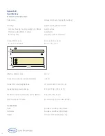
Appendix A
Normalized Water Permeability
Determining the Normalized Water Permeability (NWP)
for the Minimate TFF Capsule
Water permeability is a function of the hydraulic resistance of
the membrane at a specified transmembrane pressure (TMP).
It is related to the pore size, pore depth, and number of pores
per unit area. It is significantly affected by temperature.
Water permeability can be used as a standard upon which
to measure the effectiveness of a cleaning regime after
sample processing.
The original NWP of the Minimate TFF capsule is
essential to calculate as it is used as the basis to
determine membrane recovery, i.e., how effectively
the membrane was cleaned.
This procedure should be performed with all new Minimate TFF
capsules after the flushing and sanitization steps have been
performed. The original NWP is determined by plotting the
water filtrate flux rates at several transmembrane pressures,
typically 0.3 - 1 bar (5 - 15 psig) for UF membranes. From
the graph, the original NWP is calculated at 0.7bar (10psi).
This value is chosen for ease of calculation.
Water quality should be “Water for Injection” (WFI) or at
minimum 0.2 µm filtered DI water. Calculated water
permeability rates are “normalized” to a temperature of
20 °C by using a temperature correction factor (TCF 20 °C)
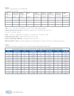
given in Table 3, page 8.
For Minimate TFF capsules that are reused from this point
on, the NWP needs only be measured and determined at a
TMP of 0.7bar (10psi).
The NWP should be measured before processing and once
again after cleaning. An example for determining NWP is
shown below.
To determine the NWP, a pressure gauge is required
on the feed and retentate ports. Filtrate pressure
should be zero (0) provided there are no restrictions
on the filtrate line and that the filtrate line is open to
atmosphere.
Recirculate the filtrate and retentate streams back to the
feed reservoir to minimize the volume of water needed.
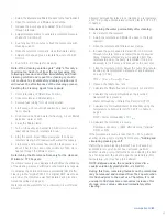
Removing air from the retentate
All air must be removed from the retentate channel before
determining the NWP as air bubbles will reduce the effective
filtration area, resulting in low NWP values.
Turn on and increase the pump speed to generate a reten-
tate flow rate of 80-100mL/min. Stop and restart the pump
several times. Observe whether any air is expelled from the
retentate line when the pump is restarted. If no air is
observed, turn off the pump and proceed to the next step.
Determining the “original” normalized water
permeability.
1. Tighten the retentate clamp to completely restrict
retentate flow. The filtrate line should be open.
2. Adjust the feed flow rate to generate a TMP of
approximately 0.33 bar (5psi).
3. Measure the filtrate flow rate and calculate the flux rate
in LMH (liters/m2/h).
4. Adjust the feed flow rate to give a TMP of approximately
0.67 bar (10psi)
5. Measure the filtrate flow rate and calculate the flux rate
in LMH (liters/m2/h).
6. Adjust the feed flow rate to give a TMP of approximately
1.0 bar (15psi)
7. Measure the filtrate flow rate and calculate the flux rate
in LMH (liters/m2/h).
8. Plot Filtrate Flux Rate vs. TMP. Draw a straight line from
zero that best fits the data between 0.3 - 1 bar (5 to 15
psig). From the curve determine the water flux rate at
0.7 bar (10 psig)
The following table may be used as an example for
recording data and calculations.
www.pall.com/lab
7


