background image

27

PALLMANN GmbH l Ein Unternehmen der Uzin Utz AG | Im Kreuz 6 | 97076 Würzburg | T49 931 27964-0 | T49 931 27964-50 I www.pallmann.net

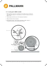
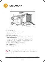
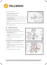
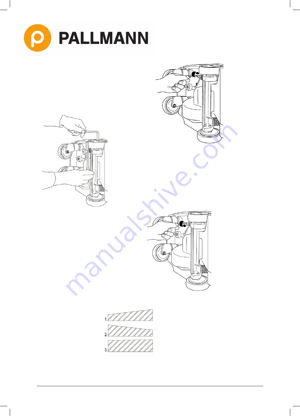
7.  Loosen the locking screw on the trolley lever next to  

  the right-hand adjustable castor.


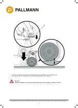
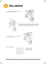
9.   Tighten the locking screw on the landing gear lever  

  next to the right-hand roller.

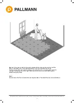
10. Check the grinding pattern.

1. readjustment required

2. readjustment required

3. optimal grinding pattern

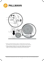
8.  Adjust the right-hand roller to the set dimension using the roller adjuster. 

  Turn  the axle of the right-hand roller with the hexagon screwdriver until 

  the right-hand roller lightly touches the tongue of the roller adjuster.

Summary of Contents for 071845

Page 1: ...kW 50Hz with gentle lifting lever COBRA CLASSIC 230 V 2 5 kW neutral 071845 COBRA CLASSIC 230 V 2 5 kW CH 075488 COBRA CLASSIC 230V 3 2 kW AUS 075490 COBRA CLASSIC 230V 2 5 kW NO 075489 Manual 076697 PALLMANN GmbH l Ein Unternehmen der Uzin Utz AG Im Kreuz 6 97076 Würzburg www pallmann net ...

Page 2: ...d Reproduction on whole or in part requires written permission from WOLFF GmbH Co KG Ungerhalde 1 D 74360 Ilsfeld Germany No liability for any damage arising from the use of this brochure Subject to alterations WOLFF GmbH Co KG Ungerhalde 1 D 74360 Ilsfeld Deutschland Fon 49 0 7062 91556 0 Fax 49 0 7062 91556 41 www wolff tools de info wolff tools de Stand 11 2018 ...

Page 3: ... CLASSIC 11 7 1 Protective clothing and equipment 11 7 2 Fitting the dust bag 11 7 3 Safety instructions regarding dust 12 7 4 Disposing of sanding dust 12 7 5 Replacing the sanding belt 13 7 6 Adjusting the sanding pressure 14 7 7 Safety instructions for electric cable and connectors 14 7 8 Connecting the COBRA CLASSIC to the mains power 15 7 9 Remarks about sanding parquet and plank floors 16 7 ...

Page 4: ...ors read these operating instructions prior to operate the machine Adherence to the safety notes helps to protect against potential dangers for health and personal safety and to prevent an improper utilisation of the machine Before starting to work make yourself familiar with the operation of the machine It s toolate if you do it while working Never allow anybody without sufficient skills and knowle...

Page 5: ...ag 3 cable with plug and coupling 4 respirator 5 Multiclip 6 operating instructions 7 hexagon socket screw key 5 mm 8 hexagon socket screw key 6 mm 9 hexagon socket screw key 10 mm 10 running wheel adjusting tool 11 tool pouch 12 fork wrench 10 mm 13 fork wrench 13 mm 14 fork wrench 24 mm 15 double fork wrench 30 36 mm 16 hearing protectors 2 Scope of delivery ...

Page 6: ...ions COBRA CLASSIC 3 1 Important components 1 pressure regulating screw 2 castor wheels 3 running wheels 4 drum cover 6 tension lever 7 cylinder head bolt 8 clamping lever 9 motor plug 10 carrying handle 11 bumper wheel 12 belt guard 13 motor 14 switch box 15 dust bag 16 cable arm 17 left hand grip 18 main lifting lever 19 right hand grip 20 gentle lifting lever ...

Page 7: ...d machine protection facilities COBRA CLASSIC is equipped with an overcurrent cutout and an no volt release The overcurrent cutout protects the machine from damage and persons from endangering in the case of short circuits The no volt release prevents uncontrolled restart of the machine after power failure The motor will not restart automatically when the power returns it will have to be switched ...

Page 8: ...the machine from the power supply before working on the machine Instructions 1 Insert the guide tube 1 into the guide tube support 7 The curved section of the tube must face toward the motor Clamp the guide tube by means of the clamping lever 6 located on the guide tube support 2 Fit the connector 8 into the both screws of th pull rod 3 Move the main lifting lever 2 into the rear position to raise...

Page 9: ... or damage could occur if the machine starts up unintentionally Disconnect the machine from the power supply before working on the machine Instructions 1 Fold down the cable arm 3 2 Move the main lifting lever 2 to the front position in order to lower the sanding drum to the floor This removes the load from the control rod 5 3 Loosen both of the wing screws a little 4 Push the handle down to detac...

Page 10: ...e off position and that the mains cable is disconnected from the motor plug 3 Lift belt tensioner 2 until locating pin 3 snaps 4 Remove the belt 1 6 Remove the knurled nut from the motor bracket 7 Now you can remove the motor Caution Injury to the operator or other persons could occur or damage could occur if the machine starts up unintentionally Disconnect the machine from the power supply before...

Page 11: ... operation LEQ 84 dB A Operating mode LEQ 87 dB A Caution Wear a respirator When using the parquet floor sander COBRA CLASSIC and when disposing of the sanding dust always wear a respirator see chapter 7 3 and 7 4 Wear the respirator which is supplied with the accessories Caution Wear safety goggles When using the parquet floor sander COBRA CLASSIC and when working on COBRA always wear safety gogg...

Page 12: ...he air wood dust can cause fires and explosions Caution Fire risk Sanding over metal parts such as nails can produce sparks which are blown into the dust bag together with the wood dust Here the glowing metal chips can still cause a fire even hours later Every time after the machine has stopped and at the end of working the sanding dust contained in the dust bag must always be disposed of immediat...

Page 13: ...re working at the sanding belt Caution Risk of cutting your hands The sanding grains of the sanding belt have sharp edges Always wear safety gloves when replacing the sanding belt Instructions for replacing the sanding belt 1 Switch the machine off 2 Disconnect the machine from the mains power 3 Open the sanding drum cover 1 4 Move the tension lever 2 forward The sanding belt which was held under ...

Page 14: ... the pressure regulating screw outwards to the red marking 2 on the screw thread 7 7 Safety instructions for electric cable and connectors Caution Mortal risk from electric shock There is a mortal risk from electric shock if the machine is used when the electric cable or connectors are damaged If the electric cable and connectors are damaged they must be replaced by a qualified electrician Caution...

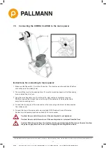
Page 15: ...as required Wind the mains cable through the curl at the end of the cable arm 3 to keep the cable away from the sanding zone 4 Connect the coupling 4 of the mains cable to the motor plug which must be disconnected from mains power 5 Connect the plug of the mains cable via a portable RCD Residual Current Protective Device to an adequately fused and earthed 230 V mains socket Caution Never switch th...

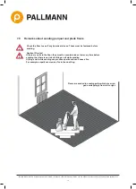
Page 16: ...right 7 9 Remarks about sanding parquet and plank floors Check the floor to see if any boards are loose These must be fastened before sanding Caution Fire risk If there are nails in the floor they must be countersunk so low every time before sanding that there is no risk of hitting a nail while sanding Hitting a nail while sanding can produce sparks and can cause a fire For example a spark can cre...

Page 17: ... Utz AG Im Kreuz 6 97076 Würzburg Telefon 49 931 27964 0 Telefax 49 931 27964 50 I www pallmann net Each sanding path corresponds to one forward and one backward movement The backward movement covers the same path as the precede forward movement ...

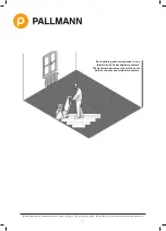
Page 18: ...e machine itself the floor is not sanded over an area of approximately 1 5 m to the wall behind the sander Turn the machine 180 and sand the remaining area of the floor also in sanding paths which are arranged overlappingly from left to right Make sure that the two areas are blended together without leaving any marks Note In most cases the floor is sanded in several procedures The whole floor area...

Page 19: ...lifting lever for the sanding drum 1 must be in the rear position The sanding drum is clearly raised from the floor The distance to the floor is approx 15 mm 2 Before starting the machine ensure that the sanding belt is tightened 3 Bring the machine into the start position 4 Set the switch to setting I Once the motor has started up switch to setting II This gradual start up procedure avoids high s...

Page 20: ...5 mm above the floor you must pull the gentle lifting lever 2 up by bending the fingers of your right hand and hold in this position 6 While you hold the gentle lifting lever 2 up push the main lifting lever 1 forward This lowers the sanding drum to approx 5 mm over the floor The gentle lifting lever 2 must always be held up because otherwise the sanding drum will be lowered to the floor ...

Page 21: ...x 49 931 27964 50 I www pallmann net 7 Now start on sanding the first path by slowly lowering the gentle lifting lever 2 while you are moving the machine forward evenly thus lowering the sanding drum to the floor Caution Move the machine at an even pace while sanding to avoid creating any dents in the floor ...

Page 22: ...ement The backward movement covers the same path as the forward movement For each forward movement move the machine about 10 cm to the right of the sanding path you have just finished Caution Never allow the machine to come to a standstill for even a short moment while sanding because this would cause an indentation in the floor This means that whenever changing between a forward and a backward mo...

Page 23: ...nd for as long as it takes for your left hand to move the main lifting lever 1 into the rear position Do not release the gentle lifting lever 2 until this has been completed Then switch the motor off and disconnect from the mains power Safeguard the machine to prevent it rolling away The sanding dust contained in the dust bag must be disposed of immediately in a fire proof non flammable container ...

Page 24: ...r 3 Open the sanding drum cover 1 4 Fold the tension lever 2 forward to relieve the tension on the sanding belt 5 Remove the sanding belt 3 to the side 6 Unscrew the retaining nut 4 The retaining nut is glued to the threads of the sanding drum shaft to ensure that it will not fall off while the COBRA is in operation To unscrew the retaining nut use the double fork wrench that comes with the machin...

Page 25: ...y in the slot on the sanding drum shaft 12 Apply metal adhesive to the retaining nut and screw it back on the sanding drum shaft Stand the machine up and lower the sanding drum to the floor to ensure that the sanding drum does not turn while you tighten the retaining nut in the next step Tighten the retaining nut securely with the enclosed double fork wrench 13 Pull the main lifting lever back to ...

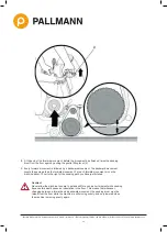
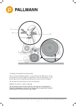
Page 26: ... C D Zust Änderungen Datum Name Datum Name Bearb Gepr Norm M Dateiname Z 01 10 2014 HeinzD 370001001 0_5 idw WOLFF Eine Marke der Uzin Utz Gruppe Oberfläche Fr Instructions 1 Turn the machine off 2 Disconnect the machine from the mains power 3 Lay the machine on its left side 4 Use the roller adjuster to adjust the the ACTUAL position of the adjustable roller 5 Check the grinding pattern If the ma...

Page 27: ...ble castor 9 Tighten the locking screw on the landing gear lever next to the right hand roller 10 Check the grinding pattern 1 readjustment required 2 readjustment required 3 optimal grinding pattern 8 Adjust the right hand roller to the set dimension using the roller adjuster Turn the axle of the right hand roller with the hexagon screwdriver until the right hand roller lightly touches the tongue...

Page 28: ...he sanding belt fails to run concentrically to the sanding drum the tension roller must be newly adjusted Caution Danger of injury Adjustments of the sanding belt while the machine is running and the sanding drum cover is open may only be performed by qualified personnel in accordance with VBG 1 41 adjustment Caution Wear safety goggles and avoid loose clothing before making these adjustments Inst...

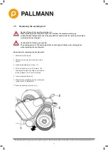
Page 29: ...ns power 10 Tighten the adjusting nuts 2 Tighten the retaining nut 1 securely 11 Close the sanding drum cover 8 5 Replacing the belt Instructions for removing the belt 1 Make sure that the motor switch is in the off position and that the mains cable is disconnected from the motor plug 2 Unscrew the knurled nut from the belt guard and open the belt guard 3 Lift belt tensioner 2 until locating pin s...

Page 30: ...eposits in it Dirt must be removed Caution Only use original WOLFF dust bags The dust bags must not be damaged mended or chafed and must not be washed If an external vacuum cleaner is used it must provide a minimum flow rate of 20 m s When using an external deduster such as a Pallmann Dust or Wolff Starvac please use the connection adapter enclosed in the delivery 8 7 Switching off and storing the ...

Page 31: ... Reduction of risks tohealth from hazardous substances emitted by machinery Part 1 Principles and specifications for machinery manufacturers DIN EN 1037 Safety of machinery Prevention of unexpected start up EN ISO 12100 Safety of machinery General principles for design Pisk assessment and risk reduktion DIN EN 60204 1 Safety of machinery Electrical equipment of machines Part 1 General requirements...

Page 32: ...n exclusively by a workshop that has suitably trained and experienced personnel at its disposal as well as the requisite work equipment We recommend using authorised service centres u In the event of planned replacement of parts planned addition of accessories or other planned technical modifications an assessment must always be carried out by an authorised service centre or us as manufacturer bef...

Reviews: