2
Palmgren Operating Manual & Parts List 9661052, 9661103, 9661202, 9661303, 9661402 & 9661501
DESCRIPTION
Palmgren Arbor Presses are designed for riveting, squeezing, bending,
punching, flattening, removing a bearing or pressing in bearings.
Removable, rotating, machined anvil has 4-slots to provide
convenient support for workpieces that vary in size and shape.
Presses are suited for work in production lines as well as in machine
shops, automotive repair shops and home workshops. Model
9661052 is a 0.5-ton press, 9661103 is a 1-ton press, 9661202 is a 2-ton
press, 9661303 is a 3-ton press, 9661402 is a 4-ton press and 9661501
is a 5-ton press.
SAFETY RULES
•
For best operation, the arbor press must be bolted to a stationary
object that is also affixed to the floor.
•
When using the press, be sure the work is mounted securely in it.
Do not attempt to use the press with the workpiece mounted on
an angle.
•
Use only accessories designed for the arbor press. Attachments
and equipment used in the pressing operation must be as strong
as the press. Use steel collars and blocks to press against the
workpiece.
•
Do not overload the press by using handle extensions (cheater
bars).
•
When not in use, the ram should be in the down position to
prevent accidents.
•
Know the arbor press and accessories. Read and understand
owner’s manual.
•
Wear a face shield or safety glasses.
•
Never place hands in jeopardy.
•
Always check your set up, i.e., see that the ram contacts
workpiece squarely before applying pressure.
•
Keep your mind on your work. Be alert.
•
Make sure workpiece, punch, anvil and accessories are securely
clamped.
•
Don’t force the arbor press or its accessories.
ASSEMBLY
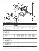
Refer to Figure 2.
•
Mount arbor press to bench or stand. Secure arbor press using
two mounting holes on the body (hardware is not supplied).
•
The 0.5, 1 and 2-Ton presses are completely assembled. The
handle needs to be installed on the 3, 4 and 5-Ton presses.
To install handle: Remove cap and bolt from handle (Ref. Nos. 12,
13 and 10). Insert handle into pinion (Ref. No. 9) and replace cap
and bolt. Secure handle in position with knob (Ref. No. 11).
•
To use with a punch: Remove pinion retaining ring and set screw
(Ref. Nos. 7 and 14) from pinion. Remove pinion from the body.
Remove ram (Ref. No. 8), mount ram upside down so the punch
hole is facing down. Replace pinion, pinion retaining ring and set
screw. Insert the punch best suited to the job. Magnet inside ram
will secure punch in position. Set screws (Ref. No. 4) will ease or
restrict the ram action. Adjust to your requirements.
MAINTENANCE
•
Oil the pinion periodically through the oil fitting, and grease the
ram rack whenever necessary. Keep a light film of oil on machined
surface to prevent rust. Keep work area clean. Clean the arbor
press of dirt and debris after every use.
•
If the ram is loose and drops by itself, loosen hex nuts and tighten
screws (Ref. Nos. 5 and 4) for adjustment. All screws should be
tightened with the same amount of pressure. Secure set screws
by tightening nuts.
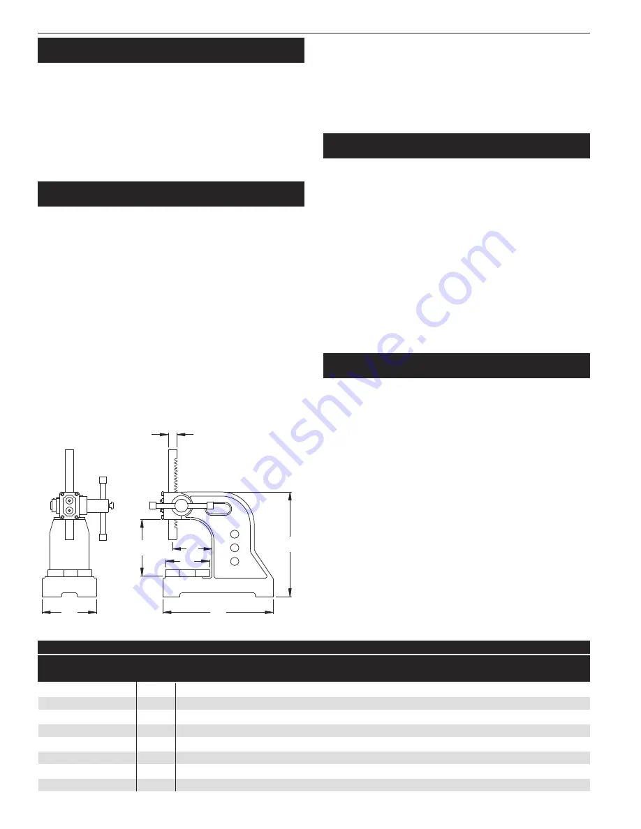
Base Length
Base Width
Height
Max. Work Height
Swing
Anvil Diameter
Ram Dimension
Ram Punch Hole
0.5-Ton
9661052
8.0"
4"
8"
4"
6.5"
3.25"
3/4" × 3/4"
3/8"
1-Ton
9661103
9.65“
5"
10"
5"
8"
4.25"
7/8" × 7/8"
3/8"
2-Ton
9661202
14"
7"
12"
6.5"
10"
6.5"
1" × 1"
1/2"
3-Ton
9661303
16"
7.5"
18"
11"
11.50”
6.5"
1.25" × 1.25"
1/2"
4-Ton
9661402
20"
10"
24"
14"
16.5"
10"
1.5“ × 1.5”
1/2"
5-Ton
9661501
24.5"
11"
31"
17.5"
18.50”
10.5"
2" × 2"
1/2"
L
W
H
A
2B
D
R × R
Model Size
Model Number
Dimension Specifications
A
W
L
B
D
H
R
Figure 1 - Dimensions


