background image

Unpacking

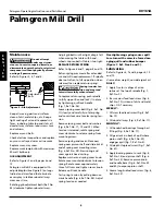
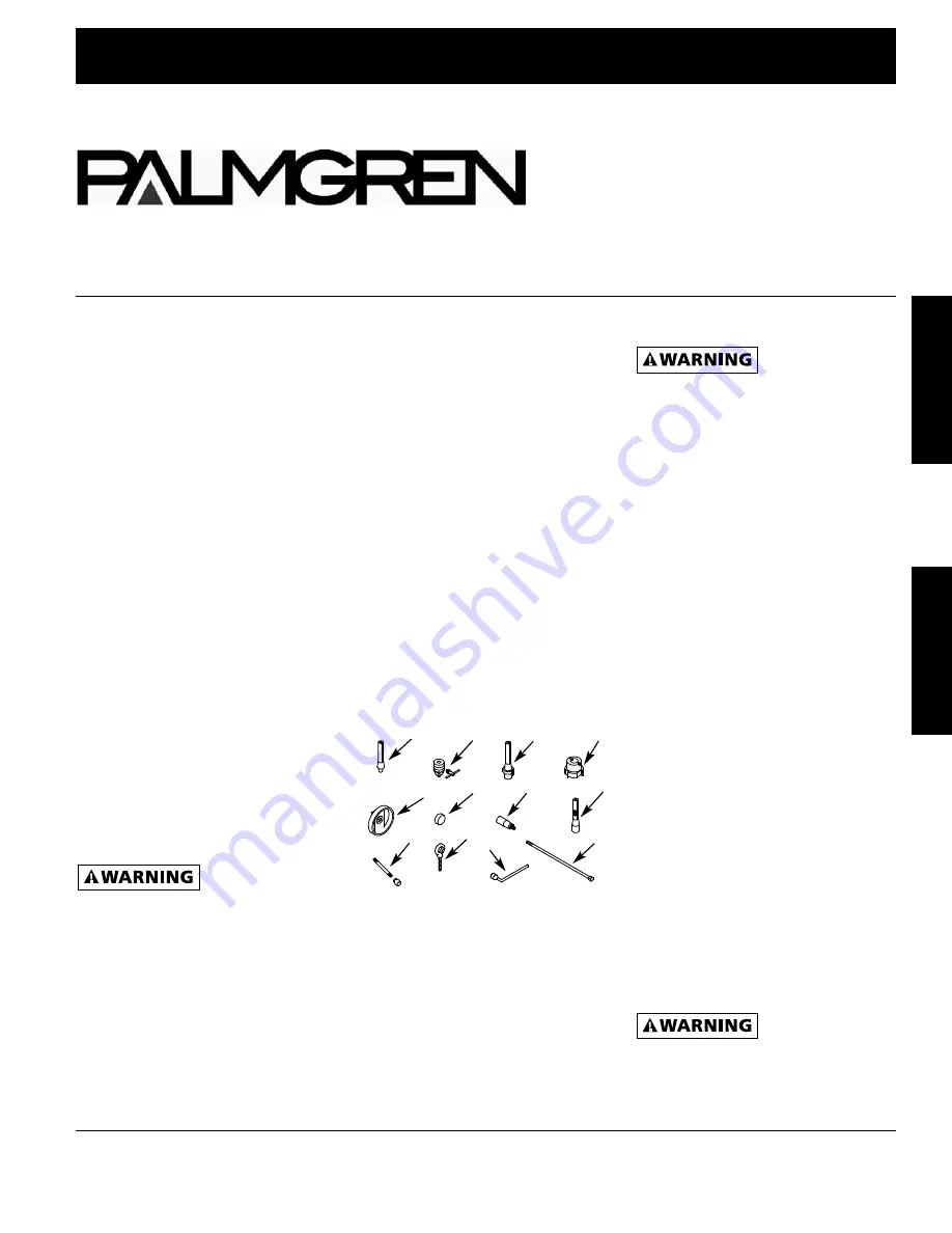
Refer to Figures 1 and 8.

Check for shipping damage. If damage
has occurred, a claim must be filed with
carrier immediately. Check for com-
pleteness. Immediately report missing
parts to dealer.

Carefully open crate and remove loose
parts box. Unbolt mill drill from ship-
ping pallet and remove from crate using
heavy duty lifting equipment such as an
overhead crane.

Eyebolts (Fig. 8, Ref. No. 46) are provided
to hoist machine. Insert the four eyebolts
into base (Fig. 8, Ref. No. 13) and secure
in position.

Be careful not to
touch overhead

power lines, piping, lighting, etc. if lift-
ing equipment is used. Mill Drill weighs
approximately 600 lbs. Proper tools,
equipment and qualified personnel
should be employed in all phases of
unpacking and installation.

Mill drill is shipped assembled except
for certain parts shipped loose in a
wooden box. Locate and account for
the following parts:

A Drill chuck arbor (on machine)
B 1/2” Drill chuck with key
C Face mill arbor

D 3” Face milling cutter
E Three Table handwheels
F Three Handwheel caps
G Four crank handles
H R8/MT3 Adapter
I

Three Quill handles and knobs

J

Four Eyebolts

K Wrench
L Drawbar (on machine)

6 pc. R8 collet set (not shown)

IMPORTANT: 

Table is coated with a

protectant. To ensure proper fit and
operation, remove coating. Coating is
easily removed with mild solvents, such
as mineral spirits, and a soft cloth.
Avoid getting cleaning solution on
paint or any of the rubber or plastic
parts. Solvents may deteriorate theses
finishes. Use soap and water on paint,
plastic or rubber components. After

A

F

E

I

J

K

L

G

H

B

D

C

31664.00-1109

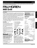
Mill Drill

Operating Instructions & Parts Manual

80161A

Please read and save these instructions. Read carefully before attempting to assemble, install, operate or maintain the product described.
Protect yourself and others by observing all safety information. Failure to comply with instructions could result in personal injury and/or
 property damage! Retain instructions for future reference.

Description

Palmgren 12-Speed Mill Drill Model 80161A is a ruggedly constructed machine pro-
viding accurate milling, drilling and boring capabilities. The fully enclosed R-8 spindle
has heavy-duty tapered thrust bearings at top and bottom of quill, adjustable depth
stop with scale, fine feed adjustment handwheel with .001” graduations and quill
lock down handle for securely clamping spindle at desired depth. One piece cast iron
head rotates 360° and travels vertically by rack and pinion.

Hinged pulley cover allows fast and easy speed changes. Large 32

3

8

x 9

1

2

” table has

dovetail ways with adjustable gibs and bronze lead screw nuts for accurate and rigid
table positioning. Table has four 5/8” T-slots, zero-setting handwheel dials with
.001” graduations, adjustable stops for longitudinal feed and cross feed way cover.

A 1½ HP, 1725 RPM, 115/230 volt, 60 Hz single-phase motor and 115v work lamp
are included. Prewired for 230v.

cleaning, cover all exposed surfaces with
a light coating of oil.

Never use highly

volatile solvents.

Non-flammable solvents are recom-
mended to avoid possible fire hazard.

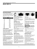
Specifications

MODEL 80161A

Horsepower . . . . . . . . . . . . . . . . . . 1

1

/

2

HP

12 Speeds. . . . . . 150, 225, 255, 350, 400

500, 850, 1200, 1500,1600

2300, 3000 RPM

Table size . . . . . . . . . . . . . . . . 32

3

/

8

x 9

1

/

2

T-slots . . . . . . . . . . . . . . . 5/8” slots, four

Swing . . . . . . . . . . . . . . . . . . . . . . . . . 16”

Spindle taper . . . . . . . . . . . . . . . R-8 with

7/16”-20 drawbar

Drilling capacity. . . . . . . . 1

1

/

4

” mild steel

1

1

/

2

” cast iron

End mill capacity . . . . . . . 3/4” mild steel

Face mill capacity . . . . . . . . 3” mild steel

Spindle stroke . . . . . . . . . . . . . . . . . . . 5”

Max. distance spindle to table . . . . . 17”

Head swivel . . . . . . . . . . . . . . . . . . . 360°

Quill diameter . . . . . . . . . . . . . . . . . . . 3”

Quill collar diameter. . . . . . 3

3

/

4

” (96mm)

Column diameter . . . . . . . . . . . . . . . 4

1

/

2

Left-right table travel
(longitudinal). . . . . . . . . . . . . . . . . . . 23”

Front-back table travel (cross) . . . . . . 7”

Motor . . . . . . . . . . . . . 1

1

/

2

HP, 1725 RPM,

115/230 volt, 23/11.5 amp,

60 Hz, single-phase

Weight . . . . . . . . . . . . . . . . . . . . . 600 lbs

Shipping weight . . . . . . . . . . . . . 666 lbs

For your own safety,

read all of the

instructions and precautions before
operating tool.

E

N
G

L

I

S

H

E
S
P

A
Ñ
O

L

Figure 1 – Unpacking

Summary of Contents for 80161A

Page 1: ...fety information Failure to comply with instructions could result in personal injury and or property damage Retain instructions for future reference Description Palmgren 12 Speed Mill Drill Model 8016...

Page 2: ...e 5 Extension cords should have a grounding prong and the three wires of the extension cord should be of the correct gauge 6 Keep visitors at a safe distance from work area 7 Keep children out of work...

Page 3: ...handle Ref No 1 into crank Ref No 2 2 Secure handle in position by tighten ing hex nut on handle 3 Secure crank onto worm shaft Ref No 6 with set screws Ref No 56 MOUNT TABLE HANDWHEELS Refer to Figur...

Page 4: ...after adjusting head CHANGING SPEED Refer to Figures 4 and 7 Palmgren mill drill is a 12 speed machine Spindle speeds are determined by location of V belts on three pulleys Always push stop button and...

Page 5: ...cise movement of table is required Scales can be zeroed by loosening dial screw Ref No 5 and rotating lead screw dial Ref No 4 until zero marks are aligned Tighten dial screw TABLE STOP BLOCKS Refer t...

Page 6: ...d cover clockwise to relax spring ten sion Remove spring cover bolt and washers Fig 6 Ref No 11 12 and 13 When tension is released rotate spring and cover clockwise to release spring from mounting scr...

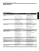
Page 7: ...deep or too fast a cut 6 Loose workpiece 1 Poorly adjusted return spring 2 Worn return spring Worn lead screw nuts 1 Loose spindle bearings 2 Loose motor pulley 3 Dull cutting tools Table is loose 1 C...

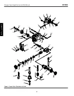
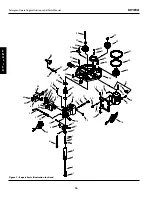
Page 8: ...Manual 80161A Figure 6 Repair Parts Illustration for Head 35 36 34 33 32 31 29 28 27 30 30 37 55 54 53 52 38 44 25 24 23 18 22 22 21 21 20 56 16 15 14 11 4 6 3 5 5 12 13 10 9 8 7 2 1 50 49 48 47 46 5...

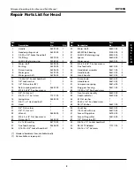
Page 9: ...d housing 26606 00 1 28 5 16 18 x 3 4 Socket head bolt 2 29 Worm shaft 26607 00 1 30 6202ZZ Ball bearing 01540 00 2 31 3AMI 15 Retaining ring 00533 00 1 32 Spacer 26608 00 1 33 Worm cover 26609 00 1 3...

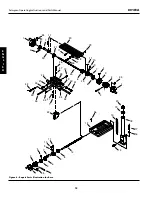
Page 10: ...Repair Parts Illustration for Head 56 53 45 44 43 42 41 40 37 35 38 55 66 67 62 63 59 51 21 21 21 57 60 18 61 69 48 58 50 24 21 20 25 26 27 23 22 19 19 28 29 32 32 68 30 41 33 17 14 15 16 8 7 6 5 11 1...

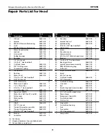
Page 11: ...26649 00 1 35 5 16 18 x 1 2 Hex head bolt 2 36 Bracket 26735 00 1 37 Contactor 26736 00 1 38 Draw bar 26652 00 1 39 Spindle lock nut 26653 00 1 40 Spindle pulley 26654 00 1 41 5 16 18 x 5 8 Hex head b...

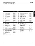
Page 12: ...80161A Figure 8 Repair Parts Illustration for Base 1 1 1 20 17 18 11 11 12 14 13 19 16 15 26 21 46 10 10 25 44 43 43 27 38 31 29 28 34 36 23 45 45 45 22 24 11 11 32 30 42 33 37 37 6 6 6 6 3 3 3 4 7 5...

Page 13: ...ocket head bolt 2 27 Stop block 26695 00 2 28 Stop block nut 26696 00 2 29 1 4 NPT x 3 8 Plug 26697 00 1 30 Table 26698 00 1 31 Longitudinal lead screw nut assy 26699 00 1 32 Table lock handle 26713 0...

Page 14: ...E N G L I S H Service Record 14 Palmgren Operating Instructions and Parts Manual 80161A Palmgren Mill Drill Date Maintenance performed Replacement components required...

Page 15: ...Notes 15 Palmgren Operating Instructions and Parts Manual 80161A E N G L I S H...

Page 16: ...ears Band saws 2 years Work stands 2 years Arbor Presses 2 years Metal Framing Equipment 2 years Accessories 1 year The obligation of Palmgren is limited solely to the repair or replacement at our opt...

Page 17: ...quipo ele vador de trabajo pesado como puede ser una gr a m vil Se proporcionan pernos de anilla Fig 8 Ref No 46 para levantar la m quina Inserte los cuatro pernos de anilla en la base Fig 8 Ref No 13...

Page 18: ...si al utilizar la sierra se produce mucho polvo 6 Est alerta y piense claramente Nunca opere herramientas mec nicas cuando est cansado ebrio o cuando est tomando medicamentos que causan somnolencia PR...

Page 19: ...d es una combinaci n del sentido com n del operador y de estar alerta en todo momento cuando se est usando la herramienta Montaje Consulte las Figuras 2 3 6 7 y 8 No intente hacer el montaje si hay pa...

Page 20: ...y libres de restos de material 2 Deslice el portabroca Ref No 50 con las mordazas retra das en el rbol y golpee el portabroca con un mazo para asentarlo en posici n Instalaci n FUENTE DE ENERGIA Consu...

Page 21: ...radora fresadora Palmgren est equipada con una rueda de mano de alimentaci n fina del husillo y un mango de sujeci n de profundidad del husillo Enganche la rueda de mano de ali mentaci n fina Fig 6 Re...

Page 22: ...a de cola de milano los tornillos de entra da la cremallera y la columna Cambie las correas V desgastadas Revise las conexiones el ctricas y cambie cualquier cable o cord n de la l nea des gastado o...

Page 23: ...de media viscosidad DIARIAMENTE 1 A ada de cinco a seis gotas de aceite en las ranuras en la parte superior del husillo Fig 7 Ref No 2 2 Aseg rese que el tornillo de entrada de alimentaci n transversa...

Page 24: ...3 18 22 22 21 21 20 56 16 15 14 11 4 6 3 5 5 12 13 10 9 8 7 2 1 50 49 48 47 46 51 40 41 19 42 39 17 45 26 43 8 Sp Manual de Instrucciones de Operacion y Lista de Partes Palmgren 80161A Figura 6 Ilustr...

Page 25: ...3 AMI 15 00533 00 1 32 Espaciador 26608 00 1 33 Cubierta de tornillo sin fin 22609 00 1 34 Tornillo de cabeza de placa 2 10 24 x 3 8 35 Escala de alimentaci n fina 26610 00 1 36 Conjunto de la rueda...

Page 26: ...24 21 20 25 26 27 23 22 19 19 28 29 32 32 68 30 41 33 17 14 15 16 8 7 6 5 11 13 12 10 9 2 1 4 3 34 31 46 46 52 54 47 65 39 49 64 36 10 Sp Manual de Instrucciones de Operacion y Lista de Partes Palmgr...

Page 27: ...6654 00 1 41 Perno de cabeza hexagonal 5 5 16 18 x 5 8 42 Mordaza 26655 00 1 43 Tornillo 26656 00 2 44 Cubierta de la barra de tiro 26657 00 1 45 Conjunto de la l mpara 26658 00 1 46 Perno de cabeza c...

Page 28: ...38 31 29 28 34 36 23 45 45 45 22 24 11 11 32 30 42 33 37 37 6 6 6 6 3 3 3 4 7 5 7 8 15 5 9 4 7 7 9 41 40 40 39 35 2 2 12 Sp Manual de Instrucciones de Operacion y Lista de Partes Palmgren 80161A E S P...

Page 29: ...bloque de tope 26696 00 2 29 Enchufe de 1 4 NPT x 3 8 26697 00 1 30 Mesa 26698 00 1 31 Tuerca del tornillo de entrada 26699 00 1 longitudinal 32 Manija de seguridad de la mesa 26713 00 2 33 Perno de...

Page 30: ...ado 2 El resorte de retorno est desgastado Las tuercas del tornillo de entrada est n desgastadas 1 Los rodamientos del husillo est n sueltos 2 La polea del motor est suelta 3 Herramientas de corte des...

Page 31: ...aladradoras 2 a os M quinas de acabado 2 a os Sierras de banda 2 a os Plataformas de soporte 2 a os Prensas de husillo 2 a os Equipos de armazonado met lico 2 a os Accesorios 1 a o La obligaci n de Pa...

Page 32: ...Registro de Servicios Manual de Instrucciones de Operaci n y Lista de Partes Palmgren E S P A O L Taladradora Fresadora Palmgren Fecha Mantenimiento efectuado Componentes de repuesto necesarios 80161A...

Reviews: