General Safety Information
(Continued)
12. Turn machine off if it jams. Drill bit
or cutter jams when it digs too
deeply into workpiece. (Motor force
keeps it stuck in the work.)
13. Clamp workpiece or brace against
column to prevent rotation.
14. Feed work into a bit or cutter
against the direction of rotation of
bit or cutter.
15. Use recommended speed for mill drill
accessory and workpiece material.
Think safety! Safety
is a combination of
operator common sense and alertness at
all times when tool is being used.
Assembly
Refer to Figures 2, 3, 6, 7 and 8.
Do not attempt
assembly if parts are
missing. Use this manual to order
replacement parts.
MILL DRILL INSTALLATION
Mill drill must be mounted to a flat
level surface. MIll drill must be level in
both cross and transverse directions. Use
shims or machine mounts if necessary.
Do not mount machine in direct sun-
light. Heat caused by sunlight may
deform plastic parts on machine.
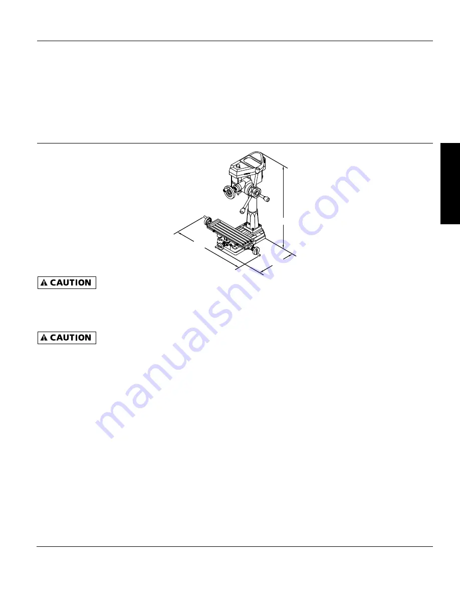
Make sure selected location has enough
clearance to accommodate full move-
ment of the table. See Figure 2 for
minimum work space required.
If stand is used, be sure to bolt mill drill
to stand and level stand to floor to min-
imize vibration. Tighten all nuts and
bolts that may have loosened in ship-
ping. Secure mill drill base to stand or
bench.
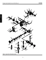
ATTACH QUILL FEED HANDLES
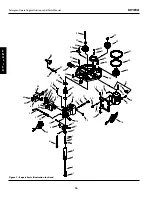
Refer to Figure 6, page 8.
1. Thread knobs (Ref. No. 37) onto han-
dles (Ref. No. 38).
2. Thread handle into hub (Ref. No. 40).
3. Repeat for remaining two knobs and
handles.
ATTACH HANDLE AND CRANK
Refer to Figure 6, page 8.
1. Thread handle (Ref. No. 1) into crank
(Ref. No. 2).
2. Secure handle in position by tighten-
ing hex nut on handle.
3. Secure crank onto worm shaft (Ref.
No. 6) with set screws (Ref. No. 56).
MOUNT TABLE HANDWHEELS
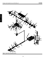
Refer to Figure 8, page 12.
1. Remove protective caps from lead
screws (Ref. Nos. 12 and 25).
2. Thread handles into table hand-
wheels (Ref. No. 1).
3. Secure two handwheels to left and
right ends of longitudinal lead screw
(Ref. No. 25) using set screws (Ref. No.
45).
4. Secure remaining handwheel to end
of cross feed lead screw (Ref. No. 12)
using set screw.
INSTALL DRAWBAR AND ARBOR
Refer to Figures 6 and 7, pages 8 and 10.
Insert draw bar (Fig. 7, Ref. No. 38) into
top of spindle. Be sure that arbor and
spindle taper are clean of all dirt, metal
chips, oil, etc. Insert chuck or face mill
cutter, adapter or R8 collet (Fig. 6, Ref.
Nos. 48, 51 or 55) into spindle and
rotate arbor to engage spindle key in
arbor keyway. Push arbor into spindle
and thread draw bar into end of arbor.
Use a wrench to tighten draw bar
securely.
TO INSTALL FACE MILL CUTTER:
1. Make sure arbor and cutter are clean
and free of debris.
2. Slide face mill cutter on arbor and
secure in position using washer and
bolt (Fig. 6, Ref. Nos. 52, 53 and 54).
TO INSTALL DRILL CHUCK:
1. Make sure arbor and chuck are clean
and free of debris.
2. Slide drill chuck (Fig. 6, Ref. No. 50)
with jaws retracted onto arbor and
tap chuck with a mallet to seat chuck
in place
Installation
POWER SOURCE
Refer to Figure 3, page 4.
The Palmgren mill drill is prewired for
230 volts, 60 Hz, single-phase power. A
qualified electrician should wire a 240
volt, 20 AMP, 3-prong plug to mill drill
line cord.
Model 80161A
3
Palmgren Operating Instructions and Parts Manual
E
N
G
L
I
S
H
Figure 2 – Required Minimum Space
80”
100”
65”

