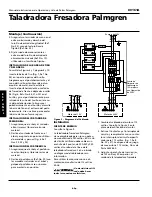
Operation (Continued)
Loosen handle and push motor mount
plate away from head to tension rear
V-belt. Tighten handle. Check belt ten-
sion and adjust if necessary. Close pulley
cover.
Secure pulley cover latches.
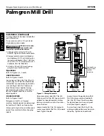
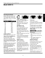
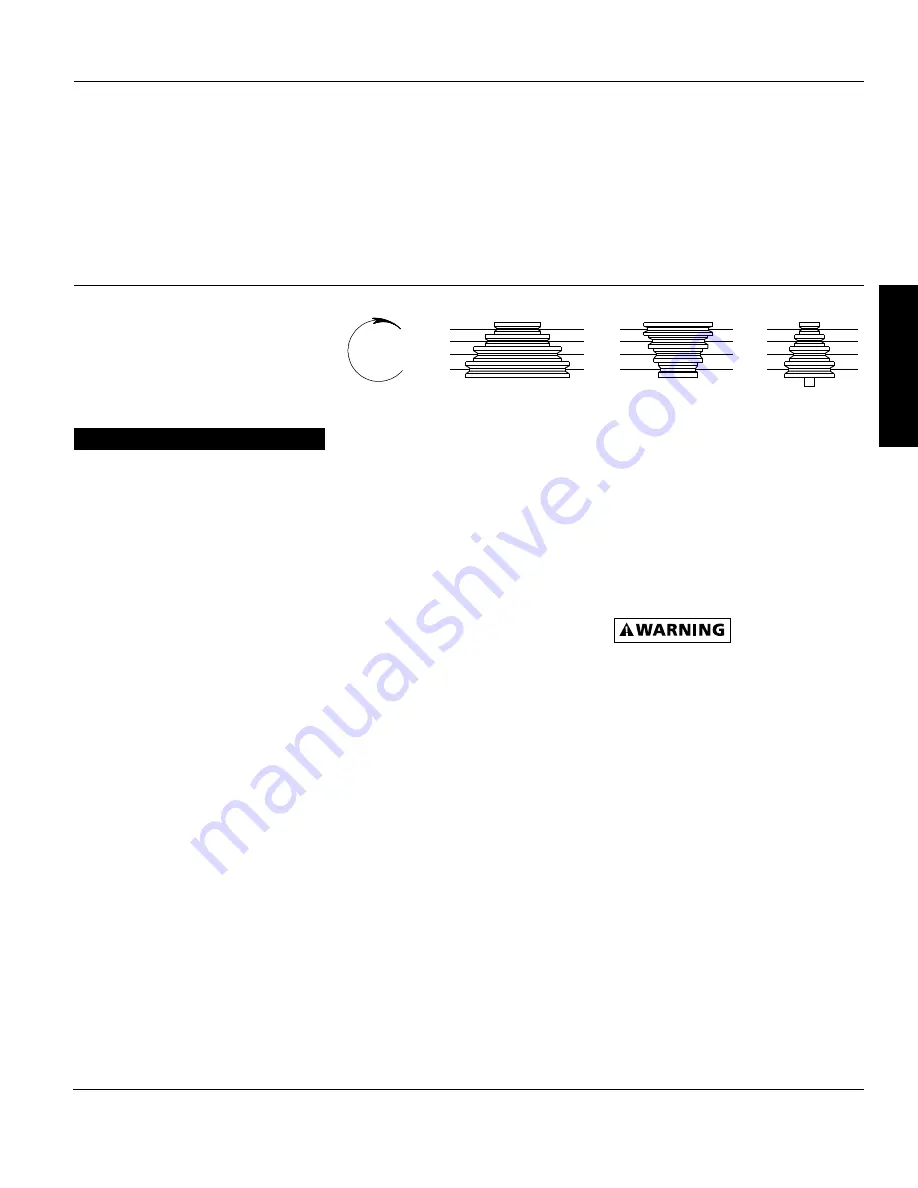
Spindle RPM
Belt Location
150
A1-4Z
225
B2-4Z
255
A1-3Y
350
C3-4Z
400
B2-3Y
500
A1-2X
850
D4-3Y
1200
C3-2X
1500
B2-1W
1600
D4-2X
2300
C3-1W
3000
D4-1W
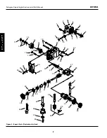
SPINDLE OPERATION
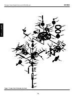
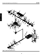
Refer to Figures 6 and 7, pages 8 and 10.
Palmgren mill drill is equipped with
spindle fine feed handwheel and spin-
dle depth lockdown handle.
Engage fine feed handwheel (Fig. 6,
Ref. No. 36) by rotating pinion knob
clockwise (Fig. 6, Ref. No. 39) until tight.
Disengage fine feed by loosening pin-
ion knob.
Spindle depth can be locked into position
by tightening quill lock handle (Fig. 7,
Ref. No. 56). Bring spindle down to
desired position and tighten quill lock
handle to hold spindle position.
DEPTH STOP
Refer to Figures 6 and 7, pages 8 and 10.
Repeated operations where depth of cut
is consistent are made easier by using
depth scale (Fig. 6, Ref. No. 44) and
depth setting knob (Fig. 7, Ref. No. 61).
Depth of cut is shown on depth scale
and indicated by depth indicator
(Fig. 6, Ref. No. 45).
Depth of cut is set by rotating depth
setting knob until desired depth is
obtained.
HANDWHEEL SCALES
Refer to Figure 8, page 12.
The cross feed handwheel and right-
hand longitudinal handwheel are
equipped with graduated collars.
One full rotation of handwheel moves
table .100”. Handwheel scales are grad-
uated in .001”.
Scales are used when precise movement
of table is required.
Scales can be zeroed by loosening dial
screw (Ref. No. 5) and rotating lead
screw dial (Ref. No. 4) until zero marks
are aligned.
Tighten dial screw.
TABLE STOP BLOCKS
Refer to Figure 8, page 12.
Longitudinal travel can be limited to
make repeated operations easier by
using the table stop blocks (Ref. No. 27).
Table stop blocks are positioned to con-
tact table stop bracket (Ref. No. 21) lim-
iting table travel.
Adjust stop blocks by loosening socket
head bolts (Ref. No. 26) and moving
stop blocks to desired position. Secure
socket head bolts.
TABLE LOCKS
Refer to Figure 8, page 12.
Mill drill table can be locked into position
using table lock handles (Ref. Nos. 32 and
41).
Longitudinal position is secured by tight-
ening lock handles on front of saddle.
Cross feed position is secured by tighten-
ing lock handles on right side of saddle.
REMOVE ARBOR
Be sure mill drill is
turned off and is dis-
connected from power source before
removing arbor.
1. Loosen draw bar with one or two
turns.
2. Tap draw bar top with mallet to free
arbor.
3. Loosen drawbar completely until
arbor drops from spindle..
OPERATING CONTROLS
Refer to Figure 7, page 10.
Power lamp (Ref. No. 64)–This lamp will
be illuminated when the machine is
connected to power source.
Emergency stop switch
(Ref. No. 65) – Press to stop machine.
The switch must be twisted clockwise
until it pops outward in order for the
machine to be operable.
Start Switch (Ref. No. 67) – Press to start
machine.
Stop Switch (Ref. No. 68) – Press to stop
machine during normal operation.
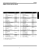
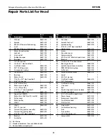
Model 80161A
5
Palmgren Operating Instructions and Parts Manual
Figure 4 – Spindle Speed Chart
B
C
A
1
2
3
4
Motor
Spindle
Spindle
Rotation
D
X
Y
W
Z
E
N
G
L
I
S
H