3
•
Do not overreach. Keep proper footing and balance.
•
Never stand on tool. Serious injury could occur if tool is tipped
over.
•
Know your tool. Learn the tool’s operation, application and spe-
cific limitations.
•
Use recommended accessories. Understand and obey all safety
instructions supplied with accessories. The use of improper
accessories may cause risk of injury to persons.
•
Do not over tighten wheel nut. Replace cracked wheel immedi-
ately. Use only flanges supplied with the grinder.
•
Adjust distance between wheel and tool rest to maintain
1
/
16
” or
less gap.
•
Handle the workpiece correctly. Whenever possible, use tool
rest to support workpiece during grinding operation. Turn tool
off if it jams.
•
Always use guards and eyeshields.
•
Clean grinding dust from beneath tool frequently.
ASSEMBLY
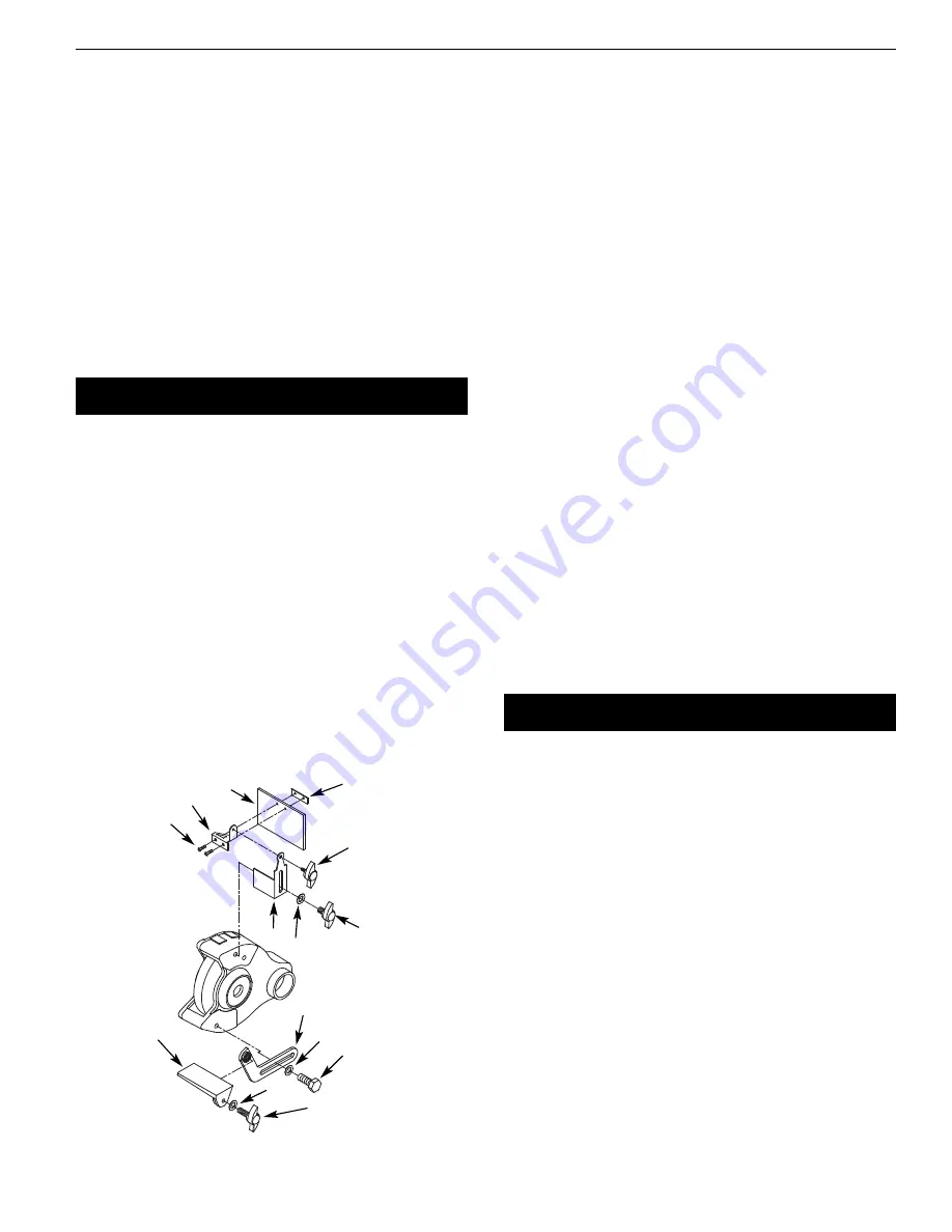
Parts to be fastened to the unit should be located and accounted
for (See List and Figure 1).
IMPORTANT: Do not attempt assembly if parts are missing. Use
this manual to order replacement parts.
A
3
/
8
-16 x
3
/
4
” Hex head bolt, 2 each
B
3
/
8
” Flat washer, 4 each
C Tool rest bracket (left & right), 2 each
D Tool rest (left & right), 2 each
E
5
/
16
” Flat washer, 2 each
F
5
/
16
-18 x 1” Knob, 2 each
G #10-24 x
3
⁄
8
” Pan head screw, 4 each
H Upper eyeshield bracket (left & right), 2 each
I
Eyeshield, 2 each
J
Lower eyeshield bracket, 2 each
K
1
⁄
4
-20 x
1
⁄
2
” Knob, 2 each
L Spark guard (left & right), 2 each
M
3
/
8
-16 x
1
⁄
2
” Knob, 2 each
Dust collector hose not shown.
TOOL REST ASSEMBLY
•
Place tool rest (D) over tool rest bracket and secure in position
with
5
/
16
-18 x 1” knob (F).
•
Attach tool rest bracket to the bottom of the left wheel guard
using one
3
⁄
8
-16 x
3
⁄
4
” hex head bolt (A) and one
3
⁄
8
” flat washer
(B). Make sure that the slot of the braket is located over the
raised boss on the guard. Tight bolts finger tight.
•
Position tool rest so that distance between tool rest and grind-
ing wheel is less than
1
/
16
”. Reposition angle of tool rest if neces-
sary. Secure all knobs and bolts.
•
Mount right tool rest in a similar manner.
EYESHIELD ASSEMBLY
•
Attach spark guard (L) to left wheel guard using
3
⁄
8
-16 x
1
⁄
2
”
knob (M) and
3
/
8
” flat washer (B).
•
Mount left upper eyeshield bracket (H) to eyeshield (I) using
two #10-24 x
3
⁄
8
” pan head screws (G) and lower eyeshield
bracket.
NOTE: Left upper eyeshield bracket is stamped “L” for identification.
•
Slide
1
/
4
-20 x
1
/
2
” knob (K) through hole at top of left spark guard
(L) into upper upper eyeshield bracket (H) and secure in
position.
•
Locate eyeshield in desired position for protecting operator
and secure all knobs and bolts.
•
Mount right eyeshield assembly in a similar manner.
DUST COLLECTOR HOSE
•
A dust collector hose has been provided with grinder. Slide
hoses onto sides of T-connector and flanges. Mount the hose
by sliding the flanges at each end over the exhaust ports on
the left and right wheel guards. Attach 2½” shop vacuum hose
to collector hose. Be sure hose is mounted securely.
DANGER:
Be sure to empty shop vacuum of all flammable materi-
al (flammable liquids and vapors, paper, wood, plastic, etc.) before
connecting vacuum to grinder. Hot sparks from grinder may ignite
flammable materials in shop vacuum.
INSTALLATION
MOUNT GRINDER
•
Mount grinder to a solid horizontal surface (hardware not pro-
vided). If mounted to metal pedestal, align mounting holes
with corresponding holes in pedestal. Insert a
1
/
4
-20 x 1¼” hex
head bolt with flat washer through base of grinder. From bot-
tom of pedestal, place a
1
/
4
” flat washer and
1
/
4
”-20 hex nut onto
the bolt. Tighten only until space between grinder base and
pedestal is
1
/
8
” (base should be flush for 82102A). Using second
nut on each bolt, jam tighten against the first to prevent loos-
ening by vibration.
•
To mount grinder to wooden bench top, use
1
/
4
x 1¼” wood
screws with flat washers beneath heads. Tighten screws until
space between grinder base and bench top is
1
/
8
” (base should
be flush for 82102A).
GROUNDING INSTRUCTIONS
WARNING:
Improper connection of equipment grounding con-
ductor can result in the risk of electrical shock. Equipment should
be grounded while in use to protect operator from electrical shock.
•
Check with a qualified electrician if grounding instructions are
not understood or if in doubt as to whether the tool is properly
grounded.
•
Inspect tool cords periodically, and, if damaged, have them
repaired by an authorized service facility.
Palmgren Operating Manual & Parts List
82082A & 82102A
J
G
C
B
B
D
E
F
A
K
L
M
I
H
Figure 1 –Left Tool Rest and Eyeshield Assembly


