background image

GETTING ST

ARTED

SAFETY

 / SPECIFICA

TIONS

ASSEMBL

Y / INST

ALLA

TION

OPERA

TION

TROUBLESHOOTING

MAINTENANCE / REP

AIR

19

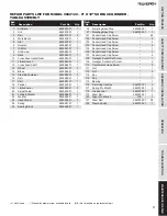
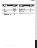
REPAIR PARTS LIST FOR MODEL 9682122 – 6” X 12” SURFACE GRINDER -  

SPINDLE ASSEMBLY

(

) Not Shown       (*) Standard hardware item available locally      (N/A) Not available as replacement part         

1

Spindle

9640006.01

1

2

Nut

9640007.01

1

3

Nut

9640008.01

1

4

Ring

9640009.01

1

5

Ring

9640010.01

1

6

Bearing Seat

9640011.01

1

7

Motor

9640012.01

1

8

Fan Cover

N/A

1

9

Motor Body

N/A

1

10 Motor Coil

N/A

1

11

Motor Rotor

N/A

1

101 Angular Contact Ball Bearing

N/A

2

102 Motor Starting

9640012.01

1

103 Bearing

N/A

1

104 Ring

N/A

1

105 Impedance Circuit

N/A

1

106 Impedance Bridle

N/A

1

107 Fan

N/A

1

108 Box

N/A

1

109 Terminal Block

N/A

1

110 Truss Head Screw

N/A

2

111 Truss Head Screw

N/A

5

112 Socket Head Cap Screw  M5x20

*

3

 Ref.

  No. 

Description 

Part No. 

Qty.

 Ref.

  No. 

Description 

Part No. 

Qty.

Summary of Contents for 9682122

Page 1: ...EN Operating Instructions Parts Manual 6 x 12 Surface Grinder Model 9682122 9640124 01 Shown with optional Magnetic Chuck 9682130 and stand 9670109...

Page 2: ...Y INFORMATION FAILURE TO COMPLY WITH INSTRUCTIONS COULD RESULT IN PERSONAL INJURY AND OR PROPERTY DAMAGE RETAIN INSTRUCTIONS FOR FUTURE REFERENCE PLEASE REFER TO BACK COVER FOR INFORMATION REGARDING D...

Page 3: ...the machine has been inspected for damage and completeness Locate any loose parts and set them aside Inspect After unpacking the unit carefully inspect for any damage that may have occurred during tr...

Page 4: ...ly trained operators You must be familiar with the proper and safe operation of a surface grinder Obtain proper training and knowledge before operating this machine Do not use the Model 9682122 Surfac...

Page 5: ...ian using genuine replacement parts Do not permit your fingers to touch the terminals of the plug when installing or removing it from the outlet Electrical safety 1 This machine must be grounded in ac...

Page 6: ...fore moving Insert and tighten the lifting eyebolt 5 Remove all the nuts and or bolts securing the machine to the pallet 6 Center an hydraulic lift forklift or other suitable overhead lifting device a...

Page 7: ...t the grinder and use the cross slide so the diamond sweeps across the wheel at a depth between 0 00039 0 001 Mounting removing a grinding wheel 1 Remove the screws holding the wheel front cover and r...

Page 8: ...ttons A are located on the right side of the machine Push the on button to start the machine and the off button to stop the machine OPERATION TABLE AND GRINDING HEAD MOVEMENT Chuck travel X axis left...

Page 9: ...into the workpiece Counterclockwise rotation raises it up The distance moved by the handwheel can be read on the inside measurement ring G The ring can be set to zero 0 00 for a reference point befor...

Page 10: ...e is securely fastened to the chuck Improper dressing of wheel 1 Tighten the dresser 2 Use proper dressing speed 3 Don t dress too deep at one time Burning spots and cracks Improper operation 1 Reduce...

Page 11: ...face grinder Only qualified maintenance people should carry out repair work on the machine Daily Carefully inspect the grinding wheel for any flaws or cracks If there any indications of issues remove...

Page 12: ...GETTING STARTED 12 For Repair Parts call 1 800 Grainger 24 hours a day 365 days a year Please provide following information Model number Serial number if any Part description and number as shown in pa...

Page 13: ...R MODEL 9682122 6 X 12 SURFACE GRINDER BASE ASSEMBLY Not Shown Standard hardware item available locally N A Not available as replacement part Ref No Description Part No Qty Ref No Description Part No...

Page 14: ...TING STARTED 14 REPAIR PARTS ILLUSTRATION FOR MODEL 9682122 6 X 12 SURFACE GRINDER ELEVATING ASSEMBLY For Repair Parts call 1 800 Grainger 24 hours a day 365 days a year Please provide following infor...

Page 15: ...39961 01 1 13 Dial 9639962 01 1 14 Washer 9639963 01 2 15 Locking Washer 9639964 01 1 16 Hand Wheel 9639965 01 1 17 Spring 9639966 01 1 18 Scale 9639967 01 1 19 Target 9639968 01 1 20 Bearing Block 96...

Page 16: ...ETTING STARTED 16 REPAIR PARTS ILLUSTRATION FOR MODEL 9682122 6 X 12 SURFACE GRINDER TABLE ASSEMBLY For Repair Parts call 1 800 Grainger 24 hours a day 365 days a year Please provide following informa...

Page 17: ...Fender 9639992 01 1 19 Limited Level 9639993 01 2 20 Adjust Screw 9639994 01 1 21 Locking Washer 9639994 01 1 22 Washer 9639995 01 1 23 Hand Wheel 9639996 01 1 24 Spring 9639997 01 1 25 Bearing Block...

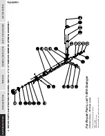
Page 18: ...TTING STARTED 18 REPAIR PARTS ILLUSTRATION FOR MODEL 9682122 6 X 12 SURFACE GRINDER SPINDLE ASSEMBLY For Repair Parts call 1 800 Grainger 24 hours a day 365 days a year Please provide following inform...

Page 19: ...1 4 Ring 9640009 01 1 5 Ring 9640010 01 1 6 Bearing Seat 9640011 01 1 7 Motor 9640012 01 1 8 Fan Cover N A 1 9 Motor Body N A 1 10 Motor Coil N A 1 11 Motor Rotor N A 1 101 Angular Contact Ball Beari...

Page 20: ...l presses tapping machines band saws lathes milling machines arbor presses abrasive finishing machines and work stands 3 YEARS The obligation of C H Hanson Palmgren is limited solely to the repair or...

Reviews: