background image

TROUBLESHOOTING (CONTINUED)

12

Palmgren Operating Manual & Parts List                                                                                                                                                                                       9683314

Motor stalls (resulting in blown fuses
or tripped circuit breakers)

Frequent opening of fuses or 
circuit breakers

Motor problems in general

Teeth ripping from blade

Motor running too hot

Coolant does not flow

Excessive blade breakage

Premature blade dulling

1. Short circuit in motor; connections loose; or

shorted terminals or worn insulation on lead
wires

2. Low voltage

3. Incorrect fuses or circuit breakers

4. Motor overloaded

1. Motor overloaded

2. Incorrect fuses or circuit breakers

Various causes

1. Teeth too coarse for work

2. Too heavy feed

3. Too slow speed

4. Vibrating workpiece

5. Gullets loaded

1. Blade tension too high

2. Blade too coarse for work (pipes especially)

3. Blade too fine for work (heavier, soft material)

4. Gears need lubrication

1. Pump motor burned out

2. Dirty screen/filter on pump

3. Loose impeller

4. Coolant level too low

1. Material loose in vise

2. Incorrect speed or feed

3. Teeth too coarse for material

4. Incorrect blade tension

5. Teeth in contact with work before 

saw is started

6. Blade rubs on wheel flange

7. Misaligned guides

8. Blade too thick for wheel diameter

1. Teeth too coarse

2. Too much speed

3. Inadequate feed pressure

4. Hard spots or scale in/on material

5. Work hardening of material (especially 

stainless steel)

6. Blade installed backwards

7. Insufficient blade tension

1. Inspect terminals in motor for damaged

insulation and shorted wires

2. Correct the low line voltage conditions

3. Install correct fuses or circuit breakers

4. Reduce load on motor

1. Reduce load on motor

2. Install correct fuses or circuit breakers

To troubleshoot and service motor consult 
qualified technician

1. Use finer tooth blade

2. Decrease feed pressure

3. Increase speed

4. Clamp work securely

5. Use coarse tooth blade or use brush to

remove chips

1. Reduce tension on blade

2. Use finer tooth blade

3. Use coarser blade

4. Check oil bath

1. Replace pump

2. Clean

3. Tighten

4. Refill coolant tank

1. Clamp work securely

2. Check Machinist Handbook

3. Check Machinist Handbook for

recommended blade type

4. Adjust to where blade does not slip on wheel

5. Place blade in contact with work after motor

is started

6. Adjust tracking

7. Adjust guide bearings

8.  Use thinner blade

1.  Use finer tooth blade

2.  Try next lower speed

3.  Decrease spring pressure

4.  Reduce speed, increase feed of saw

5.  Increase feed pressure by reducing spring 

tension

6.  Remove blade, twist inside out and reinstall

blade

7.  Increase tension to proper level

SYMPTOM

POSSIBLE CAUSES

CORRECTIVE ACTION

Summary of Contents for 9683314

Page 1: ...operating manual parts list 9683314 9 X 16 METAL CUTTING BAND SAW Read carefully and follow all safety rules and operating instructions before first use of this product 9641488 01 1216...

Page 2: ...Amps Blade speeds 82 132 170 and 235 FPM Blade size 1 x 035 x 1191 2 Blade wheels 13 Diameter cast iron Overall dimensions 67 x 23 x 431 2 Weight 625 lbs Coolant pump 2 25 Gallons per minute Coolant...

Page 3: ...flat washers Figure 20 Ref Nos 30 31 and 32 from column Figure 17 Ref No 1 Secure control box Figure 20 Ref No 33 to column using hex head bolts lock washers and flat washers INSTALL MOTOR ASSEMBLY Re...

Page 4: ...Rewire main motor to 240V Refer to Figure 3 and motor nameplate for wiring schematic Rewire coolant pump to 240V Refer to Figure 4 and wiring schematic found on the inside of motor s junction box cov...

Page 5: ...perly grounded NOTE A temporary 3 prong to 2 prong grounding adapter is available only for 115 volt operation Do not use a 3 prong to 2 prong grounding adapter unless permitted by local and national c...

Page 6: ...kbed The limit switch should be activated as soon as the cut is finished IMPORTANT Make sure the action of the limit switch is not restricted by the horizontal stop LUBRICATION All ball bearings are p...

Page 7: ...e or both blade guide brackets Ref Nos 21 and 56 must be adjusted Loosen the socket head bolts Ref No 23 and 58 Adjust the bracket to the correct position Tighten the socket head bolt Check the guide...

Page 8: ...h hex head bolts For correct tracking refer to Figure 11 Turn 1 4 revolution at a time Check the blade tension and adjust if necessary Recheck the tracking Once the proper position has been found tigh...

Page 9: ...t metals become tough and more difficult to cut and blades become dull at an accelerated rate NOTE Because much of the built up heat comes from friction between the blade and the workpiece cutting flu...

Page 10: ...ration For proper maintenance Keep saw clean and dry Sweep off spots where chips have collected and wipe off spots where coolant splashed Lubricate the unpainted surfaces with a light application of m...

Page 11: ...ies 1 Motor overloaded 2 Air circulation around motor restricted 1 Adjust vise to be square with blade 2 Reduce pressure by increasing spring tension 3 Adjust guide bearings 4 Increase blade tension a...

Page 12: ...h too coarse 2 Too much speed 3 Inadequate feed pressure 4 Hard spots or scale in on material 5 Work hardening of material especially stainless steel 6 Blade installed backwards 7 Insufficient blade t...

Page 13: ...13 Palmgren Operating Manual Parts List 9683314 NOTES...

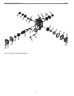
Page 14: ...9 4 5 6 15 16 11 25 26 26 26 10 10 35 14 20 20 20 20 53 9 2 7 17 24 29 29 45 31 30 30 30 3 46 47 19 19 48 27 27 18 55 22 21 21 54 60 64 65 66 63 62 61 57 58 59 52 21 51 50 1 41 40 67 38 39 34 44 27 37...

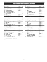
Page 15: ...1 38 3AMI 25 Retaining ring 9601900 00 2 39 Rivet 9601286 00 3 40 Angle scale 9615598 00 1 41 8 1 25 x 20mm Socket head bolt 2 42 10 1 5mm Hex nut 1 43 Plate 9615599 00 1 44 Limit switch with strain r...

Page 16: ...16 Palmgren Operating Manual Parts List 9683314 25 2 4 5 6 11 26 24 10 16 15 14 20 9 7 17 3 19 18 22 21 23 8 12 13 Figure 16 Repair Parts Illustration for Base 1...

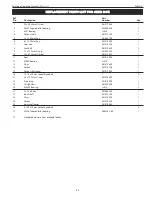
Page 17: ...pump 9615621 00 1 11 Strain relief 9601601 00 1 12 6mm flat washer 2 13 6 1 0 x 16mm Pan head screw 2 14 Base 1 15 3 8 NPT Drain plug 1 16 Pump cord 9615623 00 1 17 Cover 9615624 00 1 18 6 1 0 x 8mm...

Page 18: ...Illustration for Head 42 57 49 43 34 2 2 15 14 4 5 8 4 6 6 11 25 26 10 7 20 53 9 9 9 7 17 17 24 29 45 31 16 30 3 46 47 19 48 72 18 55 56 22 54 61 65 66 67 69 70 71 64 63 62 58 59 60 52 68 21 21 51 50...

Page 19: ...0mm Key 9615648 00 1 40 Motor 9615649 00 1 41 8 1 25mm Hex nut 4 42 Motor mount plate 9615650 00 1 43 8 1 25 x 45mm Hex head bolt 4 44 Motor tilt plate 9615615 00 1 45 8 1 25 x 25mm Socket head bolt 1...

Page 20: ...lade Guide 2 15 54 4 5 5 42 49 45 45 46 46 39 27 11 7 11 11 11 11 11 25 25 24 26 26 10 16 16 62 16 13 16 14 14 14 14 14 20 20 9 9 7 7 7 7 7 7 17 29 31 31 30 3 19 18 22 21 40 43 38 41 34 37 36 28 28 28...

Page 21: ...2 8 1 25 x 16mm Socket head bolt 1 33 Blade guard 9615681 00 1 34 10 1 50 x 25mm Socket head bolt 2 35 Scale 9615682 00 1 36 Bracket 9615683 00 1 37 5 16 Hose clamp 9600131 00 1 38 5 0 8 x 10mm Pan he...

Page 22: ...22 Palmgren Operating Manual Parts List 9683314 Figure 19 Repair Parts Illustration for Gear Box 2 15 4 5 6 26 11 24 23 25 10 20 16 14 19 9 7 3 18 17 21 27 22 8 12 13 1...

Page 23: ...9615194 00 1 11 Gear 9615195 00 1 12 6206Z Bearing 1L019 1 13 Shim 9615196 00 1 14 Gasket 9615197 00 1 15 Output shaft cover 9615198 00 1 16 10 1 5 x 20mm Socket head bolt 4 17 2 5 x 12 9mm O ring 96...

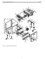
Page 24: ...ual Parts List 9683314 Figure 20 Repair Parts Illustration for Controls 2 15 15 4 5 6 6 6 26 27 26 11 47 46 48 24 23 45 49 28 29 25 10 16 14 19 9 7 3 18 14 17 21 30 31 32 33 34 21 35 36 37 39 38 40 41...

Page 25: ...15564 00 1 25 5 16 x 37 Hose 9615565 00 1 26 Clamp 9615550 00 3 27 Tee fitting 9615566 00 1 28 Plate 9615567 00 1 29 Strain relief 9617505 00 1 30 6 1 0 x 12mm Hex head bolt 2 31 6mm Lock washer 2 32...

Page 26: ...26 Palmgren Operating Manual Parts List 9683314 NOTES...

Page 27: ...27 Palmgren Operating Manual Parts List 9683314 NOTES...

Page 28: ...Metal forming equipment 2 years Accessories 1 year The obligation of Palmgren is limited solely to the repair or replacement at our option at its factory or authorized repair agent of any part that sh...

Reviews: