11
GETTING STARTED
SAFETY / SPECIFICATIONS
ASSEMBLY / INSTALLATION
OPERATION
TROUBLESHOOTING
MAINTENANCE / REPAIR
OPERATION - BLADE SELECTION
GUIDELINES
Types of materials and blade choices
To obtain the best cutting performance from your band saw,
various parameters such as material hardness, material shape
and thickness, cross cutting section of the part to be cut,
selection of the type of cutting blade, cutting speed and the
control of saw frame lowering all must be considered.
These specifications must therefore be harmoniously
combined in a single operating condition according to practical
considerations and common sense, so as to achieve an optimum
condition that does not require countless operations to prepare
the machine when there are many variations in the job to be
performed. The various problems that crop up from time to lime
will be solved more easily if the operator has a good knowledge
of these specifications.
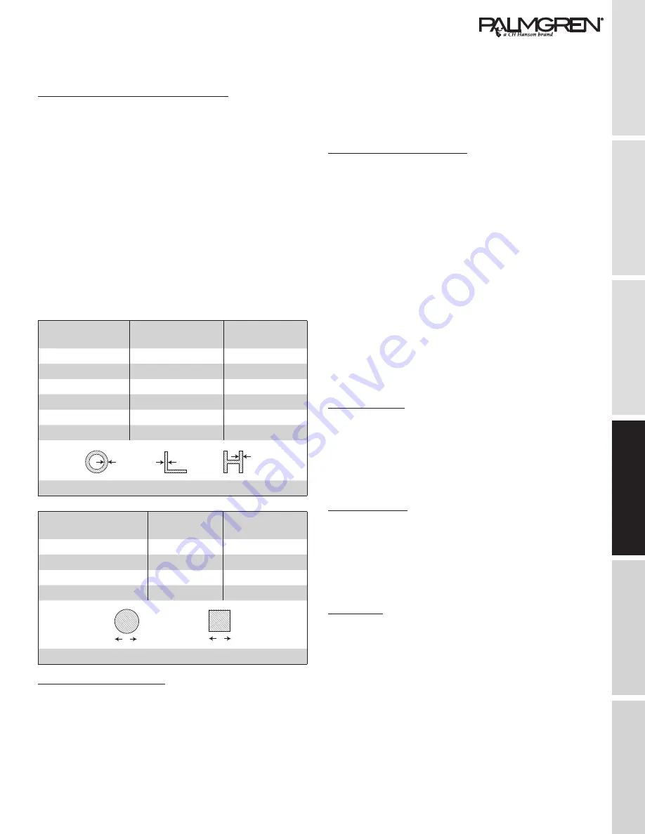
The tables below lists characteristics of materials to be cut so
that the correct blade can be chosen.
Thickness Inches
Z continuous
tooth design
Z combo
tooth design
Till .059”
14
10/14
From .039” to .078”
8
8/12
From .078” to .118”
6
6/10
From .118” to .196”
6
5/8
From .157” to .236”
6
4/6
More than .236”
4
4/6
S = Thickness
Solid Ø or L Inches
Z continuous
tooth design
Z combo
tooth design
Till 1.181”
8
5/6
From 1.181” to 60
6
4/6
From 1.574” to 3.149”
4
4/6
More than 3.54331”
3
3/4
S = Thickness L=Width
S
S
S
ø
L
Blade teeth per inch (tpi)
Choose a blade with the proper number of teeth per in (TPI)
for the material being cut. The following factors should be
considered:
• Parts with a thin and/or variable section such as profiles,
pipes and plate, need closely space teeth, so that the
number of teeth used simultaneously in cutting ranges
from 3 to 6.
• Parts with large crosscut sections and solid cores need
widely spaced teeth to allow for the greater volume of the
shavings and better tooth penetration.
• Parts made of soft material or plastic (light alloys, mild
bronze, Teflon, wood, etc. also require widely spaced teeth.
• Pieces cut in bundles require combo tooth design.
Cutting and advance speed
The cutting speed (in/min) and the advance speed (in2/min =
area traveled by the blade teeth when removing shavings) are
limited by heat build up on the tips of the teeth.
• The cutting speed is dictated by the resistance of the
material (R N/mm2), its hardness (HRC) and its dimensions
in the widest section.
• An advance speed (= lowering of the saw bow) set too fast
tends to cause the blade to deviate from the ideal cutting
path, producing misaligned cuts on both the vertical and the
horizontal plane.
• The best way to determine the proficiency of these two
parameters is to examine the chips from the cut.
• Long spiral-shaped chips indicate ideal cutting.
• Very fine or pulverized chips indicate lack of feed and/or
cutting pressure.
• Thick and/or blue chips indicate overload of the blade.
Blade break-in
When cutting for the first time, it is good practice to break in the
blade by making a series of cuts at a low advance speed
(= 12-14 in2/min on material of average dimensions compared
to the cutting capacity and solid section of normal steel with
R = 410-510 Nimm2), Generously spray the cutting area with
lubricating coolant during the break-in.
Blade structure
Bi-metal blades are the most commonly used. They consist of a
silicon-steel blade backer along with a laser welded high speed
steel (HSS) cutting edge. These type of blades are classified by a
M2, M42, M51 designation. They differ from each other because
of their hardness due to the percentage of Cobalt (Cc) and
molybdenum (Mo) contained in the metal alloy.
Blade type
Blades differ because of their construction characteristics,
such as:
• Shape and cutting angle of tooth
• Pitch
• Set shape
• Angle (rake) of the teeth


