background image

GETTING STARTED

SAFETY / SPECIFICATIONS

ASSEMBLY / INSTALLATION

OPERATION

TROUBLESHOOTING

MAINTENANCE/ REPAIR

21

ELECTRICAL CONTROL SYSTEMS - MODEL 9683315 – 10” BAND SAW

FUSE LOCK 

OUTS

MOTOR

CONTACTORS

SAFETY LOCK 

OUT

OVER

LOAD

TRANSFORMER

FOR THE COILS

Summary of Contents for 9683315

Page 1: ...EN Operating Instructions Parts Manual 9643242 01 10 Horizontal Mitering Band Saw Model 9683315 ...

Page 2: ...TY INFORMATION FAILURE TO COMPLY WITH INSTRUCTIONS COULD RESULT IN PERSONAL INJURY AND OR PROPERTY DAMAGE RETAIN INSTRUCTIONS FOR FUTURE REFERENCE PLEASE REFER TO BACK COVER FOR INFORMATION REGARDING DAYTON S WARRANTY AND OTHER IMPORTANT INFORMATION Model ____________________ Serial ____________________ Purch Date ________________ 2018 Palmgren a C H Hanson Brand All Rights Reserved ...

Page 3: ...d before use in addition to regular periodic maintenance inspections Be sure that the voltage labeled on the unit matches your power supply SAFETY RULES For you own safety read all of the instructions and precautions before operating the tool Always disconnect the machine from its power source before changing blades or carrying out any maintenance procedure even in the case of irregular machine op...

Page 4: ...not use inappropriate attachments in an attempt to exceed the tool capacity Use the right tool for the job Do not attempt to force a small tool or attachment to do the work of a large industrial tool There are certain applications for which this tool was designed Do not modify this tool and do not use this tool for a purpose for which it was not intended Do not overreach Keep proper footing and ba...

Page 5: ...ally on all four corners Remove any crating or overpacking materials which may be covering the machine Leave the machine attached to the pallet NOTE The Model 9683315 Band Saw weighs 1100 lbs Be certain any machine or devices used to lift the machine are capable of handling this weight 1 Remove all accessory items from the pallet or machine table Compare these items with the listed on page 3 2 Che...

Page 6: ... tray on the right end of the machine Under the chip tray is the tank To fill the tank D E 1 Remove the knob D that holds the chip tray to the tank 2 Grab the handles on the left and right E of the chip tray and lift the tray off to reveal the tank F F 3 Clean the tank of any dust or dirt that may have accumulated during transit 4 Fill the tank with a suitable cutting coolant The tank holds 22 lit...

Page 7: ...ON SET UP Keep your hands away from all cutting edges and moving parts Never reach under the saw or workpiece The blade is exposed in these areas and the guards cannot protect your body there Be alert to the possibility of blade binding and kickback occurring The blade covers have safety switches that stop the band saw from operating if the covers are open Do not override or disable the switches T...

Page 8: ... do not over tighten Turn the adjustment knob back counterclockwise 1 4 turn Saw guide arm adjustment AA The machine s right saw guide arm is fixed The left saw guide arm can be adjusted to accommodate varying stock widths The saw guide need to be adjusted while setting up and clamping your workpiece for cutting The best results are achieved by leaving a very small gap between the saw guide arm an...

Page 9: ...d debris from around the saw guides and both bandwheels Remove the new saw blade s protective cap if necessary 2 Form the saw blade into a loop and slip the blade under the saw guide arms and into approximate position for placement With the saw blade s teeth facing towards you place the blade around the drive and idler bandwheels 3 Twist the saw blade 90 so that its teeth between the saw guide arm...

Page 10: ...which influence band tension settings are the size of stock to be cut and desired blade life General rules of thumb are a Lower tensions will increase saw blade life b Greater tension is required as spacing is increased between the saw guide arms c Higher band speeds require greater tension Blade speed adjustment To prevent damage to the band saw speed changes must be made when the machine is runn...

Page 11: ...e crosscut sections and solid cores need widely spaced teeth to allow for the greater volume of the shavings and better tooth penetration Parts made of soft material or plastic light alloys mild bronze Teflon wood etc also require widely spaced teeth Pieces cut in bundles require combo tooth design Cutting and advance speed The cutting speed in min and the advance speed in2 min area traveled by th...

Page 12: ...pes Combo tooth 9 10 positive rake This blade type is suitable for the cutting of section bars and large and thick pipes as well as for the cutting of solid bars at machine capacity Available pitches 3 4 6 8 TEETH SET Saw teeth are slightly bent out of the plane of the saw body resulting in a wide cut in the workpiece This parameter is called tooth set Regular or raker set The cutting teeth are se...

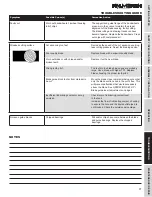
Page 13: ... Motor overloaded 1 Reduce load on motor 2 Air circulation around motor is restricted 2 Clean motor to provide normal air circulation around motor Motor stalls resulting in blown fuses or tripped circuit breakers 1 Short circuit in motor connections loose or shorted terminals or worn insulation on lead wires 2 Low voltage line conditions 3 Incorrect fuses or circuit breakers in power line 4 Motor ...

Page 14: ... use extreme care cleaning and removing hard impurities as quickly as possible Ineffective gripping of the part in the vise Check the gripping of the part being cut Tighten the vise as needed The blade gets stuck in the material Decrease the cutting advance and exert less cutting pressure Starting cut on sharp or irregular section bar Pay more attention when you start cutting Slowly and carefully ...

Page 15: ...duction materials such as castings and welding wastes etc Avoid cutting these materials In a situation where a cut has to be made use extreme care cleaning and removing hard impurities as quickly as possible Insufficient lubricating refrigerant or wrong emulsion Check level of liquid in the tank Increase the flow of lubricant Check to ensure the blade guide outlet hole and the liquid outlet pipe a...

Page 16: ... they are fastened tightly to the counter vice Adjust the blocks vertically and if necessary adjust the stop screws of the degree cuts Blade not perpendicular due to the excessive play between the guide pads and misalignment of the blocks Check and adjust the blade guides for proper tolerances See OPERATION SET UP Blade guide insert adjustments on page 8 Cut advancing too fast Decrease the speed o...

Page 17: ...ality blade Worn out blade or with chipped and or broken teeth Replace it with a new blade Wrong tooth pitch The teeth in the blade being used are probably large Use a blade with higher TPI Replace blade choosing the proper tooth pitch Blade guide block too far from material to be cut Move the blade close to material being cut so that only the blade section used in the cut is free This will preven...

Page 18: ...nning condition Check to ensure the motor pump and accident protection guarding fasteners are tight Check and adjust the blade brush as needed Six month maintenance Continuity test of the equipment potential protection circuit Coolant system Check the coolant often for signs of contamination or breakdown Drain the entire system and clean it thoroughly when coolant becomes unsuitable for further us...

Page 19: ...Motor Slide Clean and apply grease 3 MONTHS 4 Head Feed Cylinder 1 pint 0 47 liter capacity Check oil level if head fall rate is not uniform Add oil if necessary CHECK 6 MONTHS CHANGE YEARLY 5 Saw Guide Arm Slide Clean and apply oil MONTHLY 6 Head Pivot Shaft Bearing Surfaces Apply Oil MONTHLY 7 Micellaneous Vise Slide Hinges Pivot Points etc Clean and apply oil 3 MONTHS 8 Coolant Reservoir 22 lit...

Page 20: ...MAINTENANCE REPAIR TROUBLESHOOTING OPERATION ASSEMBLY INSTALLATION SAFETY SPECIFICATIONS GETTING STARTED 20 WIRING DIAGRAM MODEL 9683315 10 BAND SAW ...

Page 21: ...Y SPECIFICATIONS ASSEMBLY INSTALLATION OPERATION TROUBLESHOOTING MAINTENANCE REPAIR 21 ELECTRICAL CONTROL SYSTEMS MODEL 9683315 10 BAND SAW FUSE LOCK OUTS MOTOR CONTACTORS SAFETY LOCK OUT OVER LOAD TRANSFORMER FOR THE COILS ...

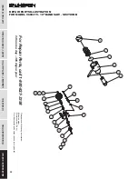
Page 22: ...CATIONS GETTING STARTED 22 REPAIR PARTS ILLUSTRATION FOR MODEL 9683315 10 BAND SAW SECTION A For Repair Parts call 1 800 827 3398 24 hours a day 365 days a year Please provide following information Model number Serial number if any Part description and number as shown in parts list ...

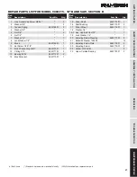
Page 23: ...2 40 Blade Cover Front 9643099 01 1 41 Blade Guard Front 9643100 01 1 42 Handle M12x45L 9643101 01 1 43 Lock Washer M6 8 44 Half Button Head Socket Screw M6x20 6 45 Blade 1 062 x158 x0 035 9643102 01 1 Ref No Description Part No Qty Ref No Description Part No Qty 46 Shaft 9643103 01 1 47 Idle Wheel 9643104 01 1 48 Cover Back 9643105 01 2 49 Oil Seal TC35528 9643106 01 2 50 Half Button Head Socket ...

Page 24: ...CATIONS GETTING STARTED 24 REPAIR PARTS ILLUSTRATION FOR MODEL 9683315 10 BAND SAW SECTION A For Repair Parts call 1 800 827 3398 24 hours a day 365 days a year Please provide following information Model number Serial number if any Part description and number as shown in parts list ...

Page 25: ...e Wheel Two Way 1 2HP BP18 125 9643147 01 1 121 Key 5x5x25 1 122 Motor 2HP 9643148 01 1 123 Control Box 9643149 01 1 124 Half Button Head Socket Screw 5x10 2 125 Blade Protector 9643150 01 1 Ref No Description Part No Qty Ref No Description Part No Qty 126 Motor Base 9643151 01 1 127 Half Button Head Socket Screw 5x10 2 128 Saw Bow Cover 9643152 01 1 129 Hex Cap Bolt Ml2x70 3 130 Lock Washer M12 9...

Page 26: ...CATIONS GETTING STARTED 26 For Repair Parts call 1 800 827 3398 24 hours a day 365 days a year Please provide following information Model number Serial number if any Part description and number as shown in parts list REPAIR PARTS ILLUSTRATION FOR MODEL 9683315 10 BAND SAW SECTION B ...

Page 27: ...Washer 3 8 2 5 Nut 3 8 2 6 Nut 1 4 1 7 Washer 1 4 1 8 Lock Washer 1 4 1 9 Brush 9643169 01 1 10 Set Screw 1 4 x1 4 1 11 Brush Connecting shaft 9643170 01 1 12 C Ring S15 9643171 01 2 13 Bearing 6002 9643172 01 2 14 Brush Bracket 9643173 01 1 15 Driver Shaft 9643174 01 1 16 Shaft Bushing 9643175 01 2 17 Driver Wheel 9643176 01 1 18 Washer 1 4 1 19 1 Hex Cap Bolt 1 4x112 1 19 Lock Washer 1 4 1 20 Ad...

Page 28: ...CATIONS GETTING STARTED 28 REPAIR PARTS ILLUSTRATION FOR MODEL 9683315 10 BAND SAW SECTION C For Repair Parts call 1 800 827 3398 24 hours a day 365 days a year Please provide following information Model number Serial number if any Part description and number as shown in parts list ...

Page 29: ...1 44 Lock Washer M8 2 45 Hex Cap Bolt M8x25 2 46 Spring Base 9643204 01 1 47 Lower Bracket Shaft 9643205 01 1 48 C Ring S12 9643206 01 2 49 Nut M16 2 Ref No Description Part No Qty Ref No Description Part No Qty 50 Thread M16x260L 9643207 01 1 51 Spring Pin 06x3OL 9643208 01 1 52 Spring Support 9643209 01 1 53 Spring Plate 9643210 01 1 54 Saw Bow Sping A 070x308x9 9643211 01 1 57 C Ring S16 964321...

Page 30: ...CATIONS GETTING STARTED 30 REPAIR PARTS ILLUSTRATION FOR MODEL 9683315 10 BAND SAW SECTION C For Repair Parts call 1 800 827 3398 24 hours a day 365 days a year Please provide following information Model number Serial number if any Part description and number as shown in parts list ...

Page 31: ...lunger Seat 9643240 01 1 109 Flat Head Screw M6x16 2 110 Ball Plunger 9643241 01 1 110 Wire Locking PG13 5 CSA 9643118 01 2 111 Work Stop Rod 9643245 01 1 Ref No Description Part No Qty Ref No Description Part No Qty 112 Lock Handle 9643246 01 1 113 Work Stop bracket 9643247 01 1 114 Work Stop 9643248 01 1 115 Lock Knob 9643249 01 1 116 Plate 9643448 01 1 117 Lock Washer M12 9643449 01 1 118 Hex C...

Page 32: ...ll presses tapping machines band saws lathes milling machines arbor presses abrasive finishing machines and work stands 3 YEARS The obligation of C H Hanson Palmgren is limited solely to the repair or replacement at our option at its factory or authorized repair agent of any part that should prove inoperable Purchaser must lubricate and maintain the product under normal operating conditions at all...

Reviews: