background image

Page 47

TU2506 

ǀ

 TU2807V

US

4.15

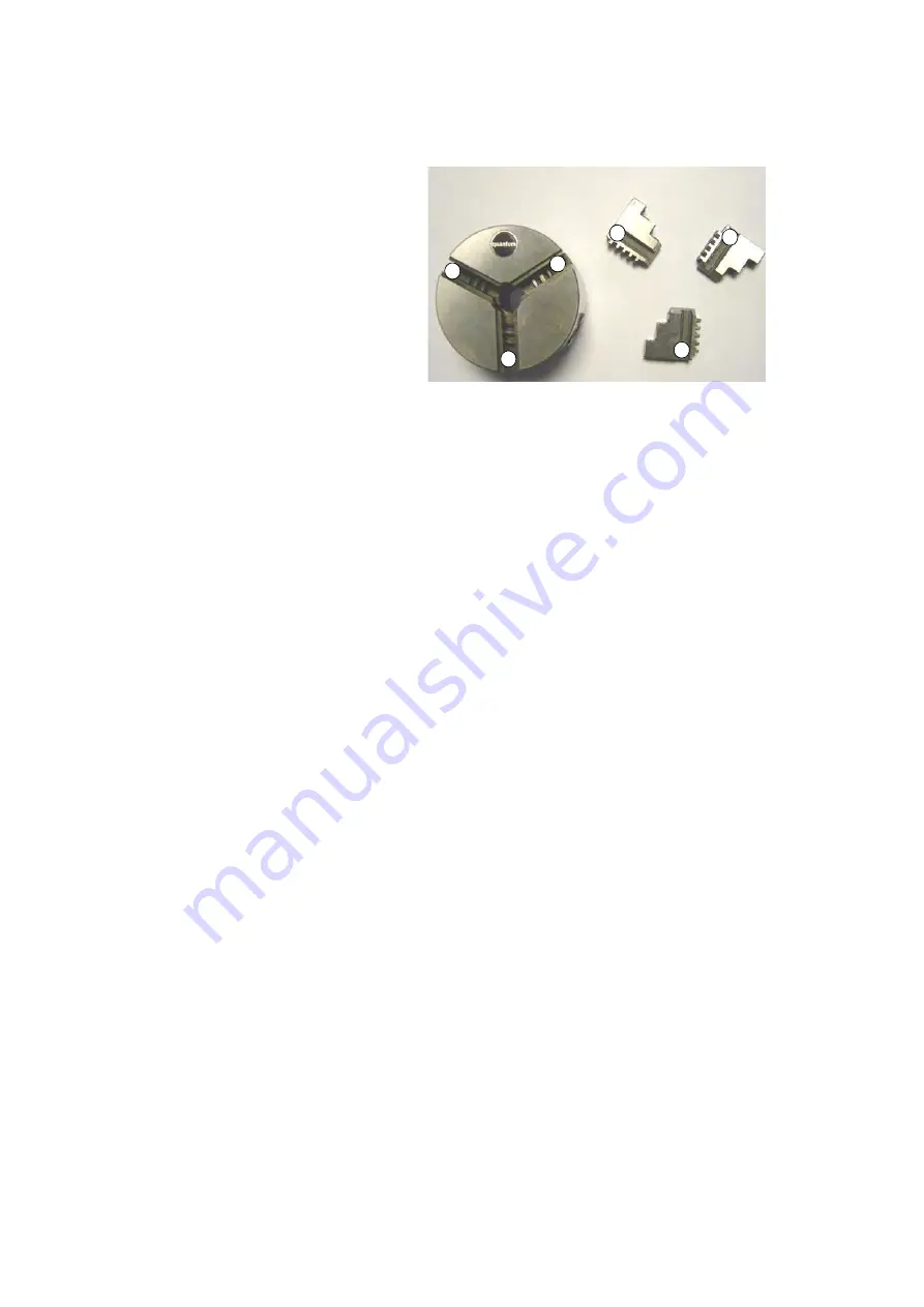
Replacing the clamping jaws on the lathe chuck

The clamping jaws and the three-jaw chuck
are provided with numbers. Check before
the change, if the numbers are readable
and, if necessary, mark the jaws and their
primary position. Insert the clamping jaws at
the correct position and in the right order into
the three-jaw chuck.

After the replacement, bring the jaws com-
pletely together in order to see if they are
inserted correctly.

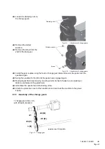
Fig.4-17:

Three- jaw chuck / clamping jaws

1

2

3

3

2

1

Summary of Contents for TU 2506

Page 1: ...US Item No 9684509 Operating manual Version 2 2 2 Lathe...

Page 2: ...Individual protection gear 14 1 12 Safety during operation 14 1 13 Disconnecting the lathe and making it safe 15 1 14 Using lifting equipment 15 1 15 Mechanical maintenance work 15 2 Technical data 2...

Page 3: ...huck 37 4 8 Adjusting the speed 38 4 8 1 Changing the speed range 39 4 8 2 Speed table TU2506 39 4 8 3 Speed table TU2807V 39 4 9 Adjusting the feed 40 4 9 1 Selector switches 40 4 9 2 Changing the ch...

Page 4: ...parts TU2807V 7 1 Top slide 75 7 2 Cross slide 76 7 3 Bed slide 77 7 4 Tailstock 78 7 5 Machine bed 79 7 6 Feed gear 1 of 2 80 7 7 Feed gear 2 of 2 81 7 8 Headstock 1 of 2 82 7 9 Headstock 2 of 2 83 7...

Page 5: ...long service life In the paragraph Maintenance all maintenance works and functional tests are described which the operator must perform in regular intervals The illustration and information included...

Page 6: ...prohibition warning and mandatory signs as well as the warning notes on the lathe Consult OSHA state and local regulations in order to determine compliance danger and risks to the operator Always kee...

Page 7: ...personnel WARNING Risk A danger that might cause serious injury or death to personnel CAUTION Danger or unsafe procedure that might cause injury to personnel or dam age to property ATTENTION Situation...

Page 8: ...ified without authorization then the lathe is being used improperly We do not take liability for damage caused by improper use We would like to stress that any modifications to the construction or tec...

Page 9: ...never cleaning or maintenance work is being carried out WARNING The lathe may only be used with the safety devices activated Disconnect the lathe from main power source whenever you detect a failure i...

Page 10: ...ood the operating manual be familiar with all safety devices and regulations be able to manipulate the machine 1 5 5 Additional qualification requirements For work on electrical components or equipmen...

Page 11: ...ed that there is no resulting danger for personnel or objects WARNING If you bypass remove or override a safety device in any other way you are endangering yourself and other personnel working with th...

Page 12: ...dle head of the lathe is equipped with a fixed separating protective cover The locked position is monitored by means of an interlock switch INFORMATION It is not possible to start the machine until th...

Page 13: ...ift with the machine stopped once a week with the machine in operation after every maintenance and repair operation Lathe chuck key General check Equipment Check OK Lathe chuck guard Fitted firmly bol...

Page 14: ...ndanger other people and cause damage to equipment Avoid unsafe working practices Make sure your work does not endanger anyone Clamp the workpiece tightly before activating the lathe For clamping work...

Page 15: ...t the lifting and load suspension gear is of sufficient load capacity and in perfect condition Observe the rules for preventing accidents issued by your association for the prevention of occupational...

Page 16: ...Screw size 3 4 Dia 10 TPI Longitudinal Feed Dial graduation 0 01 1rev 0 780 0 02 1rev 1 180 Thread Cutting Pitches Inches tpi 8 9 9 10 11 12 12 5 14 16 18 20 22 24 25 28 32 36 40 44 48 50 56 Thread Cu...

Page 17: ...are depending on one another it is not possible to use it in order to reliably determine if it is necessary to take fur ther preventive measures or not Tailstock sleeve diameter 30mm 1 181 Tailstock s...

Page 18: ...tor is exposed to the noise Furthermore the admissible pollution level may be different from one country to another due to the national regulations This information regarding the noise emission should...

Page 19: ...U2506 Fig 2 1 Dimensions installation plan TU2506 A A A A 1115 43 9 1250 49 2 475 18 7 100 4 520 20 5 585 23 520 20 5 117 4 6 120 4 7 210 8 3 140 5 5 160 6 3 660 26 114 4 5 764 30 200 7 9 300 11 8 350...

Page 20: ...TU2807V Fig 2 2 Dimension installation plan TU2807V A A A A 1290 50 8 1370 54 240 9 5 722 28 4 180 7 160 6 3 425 16 7 160 6 3 130 5 1 210 8 3 838 33 1275 50 2 440 17 3 120 4 7 540 21 5 660 26 200 7 9...

Page 21: ...Page 21 TU2506 TU2807V US 2 9 Distance between centres height of centres TU2506 Fig 2 3 Distance between centres height of centres...

Page 22: ...Page 22 TU2506 TU2807V US 2 10 Distance between centres height of centres TU2807V Fig 2 4 Distance between centres height of centres...

Page 23: ...Follow the instructions and information on the box WARNING Use of unstable lifting and load suspension gear that breaks under load can cause very serious injuries or even death Check that the lifting...

Page 24: ...uld fulfill certain criteria Observe the following items The device must only be installed and operated in dry ventilated places Avoid places nearby machines generating chips or dust The site has to b...

Page 25: ...d due to the load suspen sion 3 4 3 Installation WARNING Danger of crushing and overturning The lathe must be installed by at least 2 people Check the horizontal orientation of the base of the lathe w...

Page 26: ...sual inspection Check the oil level in the inspection glass of the feed gear Fig 5 2 Oil inspection glass of the feed gear on page 55 3 5 3 Run test Check smooth running of all spindles Check the stat...

Page 27: ...the flange to a diameter as a H7 fit Put the jaw chuck onto the flange INFORMATION Position the chuck on the spindle nose step and tap it in with rubber faced hammer distribute uniformly easy strokes...

Page 28: ...Page 28 TU2506 TU2807V US 3 7 2 Chuck flange TU2506 TU2807V Fig 3 1 Chuck flange TU2506 TU2807V Unit mm...

Page 29: ...l gauge at the spindle nose with an e g felt tipped pen Attach the collet chuck holder to the spindle flange hand tighten the nuts Tighten in the nuts stepwise once and uniformly alternating at least...

Page 30: ...Page 30 TU2506 TU2807V US 3 7 4 Mounting of movable rest TU2506 Fig 3 3 Movable rest TU2506 3 7 5 Mounting of movable rest TU2807V Fig 3 4 Movable rest TU2807V...

Page 31: ...Page 31 TU2506 TU2807V US 3 7 6 Mounting of steady rest TU2506 Fig 3 5 Steady rest TU2506 3 7 7 Mounting of steady rest TU2807V Fig 3 6 Steady rest TU2807V...

Page 32: ...iately of any modification Safety during operation on page 14 4 2 General working advice coolant Friction during the cutting process causes high temperatures at the cutting edge of the tool The tool s...

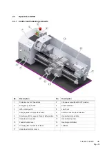
Page 33: ...OFF position 3 Emergency stop button 4 Switch ON OFF 5 Lathe chuck guard 6 Jaw chuck 7 Change gears and pitch feed table 8 Selector switch for feed direction 9 Selector switch for speed of feed of lat...

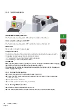
Page 34: ...clockwise The labeling L means left handed rotation ATTENTION Wait until the rotation of the spindle has come to complete standstill before changing the direction of rotation by actuating the change o...

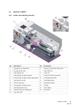
Page 35: ...Push button ON 5 Lathe chuck guard 6 Jaw chuck 7 Change gears and pitch feed table 8 Selector switch for feed direction 9 Selector switch for speed of feed of lathe saddle 10 Handwheel lathe saddle 11...

Page 36: ...ns right handed rotation clockwise The labeling L means left handed rotation ATTENTION Wait until the rotation of the spindle has come to complete standstill before changing the direction of rotation...

Page 37: ...ged or deformed WARNING Do not clamp any workpieces that exceed the permitted chucking capacity of the lathe chuck The clamping force of the chuck is too low if its capacity is being exceeded The jaws...

Page 38: ...the speed can be regulated within the corresponding speed ranges with the aid of a frequency converter The speed can then be adjusted using the potenti ometer on the control panel of the lathe In ord...

Page 39: ...e It must not be damaged or overstretched Tighten the tension pulley and fasten the nut again The correct tension of the synchronous belt has been reached when you can still bend it approximately 3 mm...

Page 40: ...lecting the feed speed or the thread pitch Change the change gears if the required thread pitch cannot be obtained with preinstalled gear set 4 9 2 Changing the change gears The change gears for the f...

Page 41: ...again Swing the quadrant to the left until the gears have engaged again Readjust gear flank clearance by inserting a normal sheet of paper as an adjusting or distance aid between the gearwheels Immob...

Page 42: ...ivide lead screw pitch tpi threads per inch by gear transmis sion ratio The number 10 in the above calculation is the tpi pitch of the lead screw The number 40 is the number of the teeth on 1st drive...

Page 43: ...in a way that you may assemble the required combination of the gears to cut a thread without having to look up the details Ligatures from one figure to the following one represent the caming of one g...

Page 44: ...s reached Fig 4 13 example of gear wheel combination for TU2506 The designation a b c of the threading table is the meaning of the position of selector switch on feed gear 4 11 Engaging lever The auto...

Page 45: ...lide Clamp the top slide again 4 12 2 Cross adjustment of the tailstock See also Turning Speeds Feeds on page 48 The cross adjustment of the tailstock is used for turning long thin shafts Loosen the l...

Page 46: ...rkpiece into the lathe chuck When the workpiece is being clamped unprofessionally there is a risk of injury as the work piece may fly off or the jaws may break The following examples do not show all p...

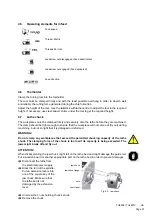
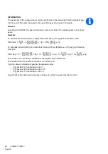
Page 47: ...fore the change if the numbers are readable and if necessary mark the jaws and their primary position Insert the clamping jaws at the correct position and in the right order into the three jaw chuck A...

Page 48: ...g speed feed rate and depth of cut are known as cutting conditions Cutting conditions are determined by the machinability rating Machinability is the comparing of materials on their ability to be mach...

Page 49: ...00 350 300 240 200 175 AISI 1055 1060 1065 1070 1074 1080 1085 1090 1095 HR N A CD HR N A CD N CD Q T N Q T Q T Q T 125 to 175 175 to 225 225 to 275 275 to 325 325 to 375 375 to 425 100 90 65 55 45 30...

Page 50: ...the speed to use Try to get to the speed which is nearest to the calculated RPM but if you can t consider these conditions Are you roughing or finishing If you are roughing go slower If you are finis...

Page 51: ...is the rate at which the tool will advance for every revolution of the workpiece Fig 4 20 Feed per revolution auf Seite 51 The feed rate is determined by the size of the chip that the tool can withst...

Page 52: ...must be kept to a minimum to assure proper rigidity The required workpiece finish will also affect the feed rate selection Finer finish requirement will require a slower feed rate selection When usin...

Page 53: ...th sufficient capacity for the amount of liquid to be col lected liquids and oils are not spilt on the ground Clean up any spilt liquid or oils immediately using proper oil absorption methods and disp...

Page 54: ...g Before restarting run a safety check Safety check on page 13 WARNING Before connecting the machine you must check that there is no danger for personnel and the lathe is undamaged 5 2 Inspection and...

Page 55: ...the feed gear First after 200 hours in ser vice then after every year Feed gear Oil change Use an adequate collector vessel with sufficient capacity for the oil change Unscrew the bolt of the outlet U...

Page 56: ...l is not covered For repairs only use Proper and suitable tools Parts purchased from company or its authorized agent every month Lathe TU2506 TU2807V Lubricate Lubricate all oilers with machine oil do...

Page 57: ...Page 57 TU2506 US 6 Spare parts TU2506 6 1 Top slide Fig 6 1 Top slide TU2506 108 107 24 104 19 22 20 7 1 3 4 5 6 8 10 11 39 34 36 33 13 9 12 37 35 16 17 18 105 19 26 14 32 23 110 111 109 38 106 14 13...

Page 58: ...e 58 TU2506 US 6 2 Cross slide Fig 6 2 Cross slide TU2506 27 26 61 68 66 139 69 65 117 124 69 64 62 122 57 118 117 85 121 48 58 126 127 42 56 45 46 119 55 85 54 50 79 49 119 64 116 115 59 52 43 45 85...

Page 59: ...TU2506 US 6 3 Bed slide Fig 6 3 Bed slide TU2506 74 73 84 83 72 139 86 82 87 80 82 102 131 130 133 132 89 129 99 128 134 136 137 138 100 96 71 101 75 1 70 75 2 99 97 98 90 91 92 95 96 93 130 141 140...

Page 60: ...ge 60 TU2506 US 6 4 Tailstock Fig 6 4 Tailstock TU2506 917 916 915 914 912 913 911 951 947 907 906 919 952 944 905 904 933 942 934 935 936 938 937 948 921 931 922 945 941 932 950 949 930 940 939 946 9...

Page 61: ...Page 61 TU2506 US 6 5 Machine bed Fig 6 5 Machine bed TU2506 A B A B 404 441 2 441 3 405 607 441 612 606 605 604 611 602 603 238 276 601 600 239 298 297 295 240 243 242 295 245 245 441 1...

Page 62: ...Page 62 TU2506 US 6 6 Feed gear 1 of 2 Fig 6 6 Feed gear TU2506 1 of 2 342 331 332 335 334 336 351 360 361 335 352 338 339 338 339 340 340 337 341 353 337 312 312...

Page 63: ...63 TU2506 US 6 7 Feed gear 2 of 2 Fig 6 7 Feed gear TU2506 2 of 2 301 301 302 304 314 349 348 310 350 305 307 308 348 309 315 343 344 345 330 316 328 319 320 346 347 325 325 321 324 327 328 329 330 31...

Page 64: ...2 Fig 6 8 Headstock TU2506 1 of 2 470 403 404 404 424 1 424 2 427 476 428 425 439 438 438 442 442 437 475 440 436 434 433 435 472 473 414 415 419 416 420 417 443 423 421 208 209 431 430 2 430 430 1 20...

Page 65: ...6 9 Headstock 2 of 2 Fig 6 9 Headstock TU2506 2 of 2 414 408 406 256 258 257 262 261 260 259 407 251 250 259 237 243 236 2 236 1 243 237 235 231 958 957 229 228 230 244 403 405 404 269 268 272 267 26...

Page 66: ...Page 66 TU2506 US 6 10 Change gear Fig 6 10 Change gear 343 344 345 518 517 417 255 503 519 505 516 505 516 502 505 516 523 524 525 521 520 521 522...

Page 67: ...Page 67 TU2506 US 6 11 Operating panel Fig 6 11 switching elements USA 953 960 954 955 956 961 273 278 272 268 269 267 266 263 962 963 964 965...

Page 68: ...DIN 125 1 4 mm 34 Countersunk screw 2 DIN EN ISO 7046 1 H M5 x 8 35 Shaft 1 0342500135 36 Splinter shield 1 0342500136 37 Hexagonal case 1 0342500137 38 1 Socket head screw 2 GB 70 85 M3 x 8 38 2 Nut...

Page 69: ...B 8 4 115 Set screw 5 M5x15 03425001115 116 Hexagon nut 5 ISO 4032 M5 117 Socket head screw 7 GB 70 85 M5 x 16 118 Guide rail bed slide 1 03425001118 119 Socket head screw 4 GB 70 85 M5 x 25 121 Bed s...

Page 70: ...10 277 Strain relief connection cable 1 PG 19 03425001277 278 Threaded pin 1 DIN 915 M5 x 12 279 Cover switch housing 1 03425001279 295 Deep groove ball thrust bearing on one side working 2 51102 034...

Page 71: ...head screw 4 GB 70 85 M5 x 10 423 Shaft nut 1 42303425001 424 1 Shaft 1 034250014241 424 2 Case 1 034250014242 425 Toothed belt 1 230XL 070 0395350 427 Toothed belt disk 1 03425001427 428 Circlip 1 DI...

Page 72: ...M3 x 5 606 Cover plate identification plate 1 03425001606 US 607 Thread cutting table 1 03425001607 607 Thread cutting table TU2506 03425006607 US 611 Chip pan 1 03425001611 612 Rubber 1 03425001612...

Page 73: ...954 Transformer 1 115V 24V 60Hz 03425001954 115V 955 Magnetic contactor 1 0460025 956 Limit switch 1 03425001274 957 1 Cover capacitor 1 03425001957 957 2 Cover capacitor 1 034250019581 958 1 Capacit...

Page 74: ...Page 74 TU2506 US...

Page 75: ...parts TU2807V 7 1 Top slide Fig 7 1 Top slide TU2807V A A 39 34 34 49 32 35 12 5 3 1 2 10 11 8 9 12 31 30 20 7 15 105 109 17 4 16 110 18 21 21 22 23 25 26 27 147 19 145 19 146 144 15 14 13 13 24 38 2...

Page 76: ...Page 76 TU2807V US 7 2 Cross slide Fig 7 2 Cross slide A A 48 43 44 46 45 46 47 49 50 59 54 55 126 125 127 118 58 85 139 69 69 62 124 64 117 65 66 68 26 27 61 122 121 118 125 52 42 41 21 41 42...

Page 77: ...Page 77 TU2807V US 7 3 Bed slide Fig 7 3 lathe saddle TU2807V A A 78 77 38 79 78 80 81 90 91 92 96 95 94 93 93 71 87 72 83 84 73 74 86 82 29 28 129 128 89 88 134 135 136 99 98 97 71 138 137...

Page 78: ...S 7 4 Tailstock Fig 7 4 Tailstock A A 927 928 930 925 929 933 906 906 939 908 949 942 905 946 909 916 910 911 912 919 921 920 922 923 934 950 940 904 941 932 945 938 935 938 948 902 936 937 931 40 917...

Page 79: ...Page 79 TU2807V US 7 5 Machine bed Fig 7 5 Machine bed B A B A 605 604 405 441 3 441 2 441 1 404 402 441 612 602 603 238 611 601 245 245 242 295 247 240 295 40 297 298 239...

Page 80: ...Page 80 TU2807V US 7 6 Feed gear 1 of 2 Fig 7 6 Feed gear TU2807V 1 of 2 342 351 336 334 335 360 361 335 352 332 331 338 339 337 340 341 312 338 339 340 337 353 312 311...

Page 81: ...V US 7 7 Feed gear 2 of 2 Fig 7 7 Feed gear TU2807V 2 of 2 343 344 345 330 316 328 319 320 301 301 304 302 314 348 306 309 305 307 308 350 303 315 354 311 310 348 349 346 347 321 325 326 325 326 324 3...

Page 82: ...ig 7 8 Headstock 1 2 D D 425 428 440 454 427 454 440 424 470 418 419 261 262 257 259 260 258 256 407 406 408 414 414 415 417 416 420 443 423 421 430 436 249 236 236 235 237 455 453 424 440 438 438 439...

Page 83: ...age 83 TU2807V US 7 9 Headstock 2 of 2 Fig 7 9 Headstock 2 2 206 430 232 207 708 231 711 425 427 420 416 723 722 721 730 731 951 733 734 727 728 729 269 274 710A 418 725 735 710 419 417 423 443 957 95...

Page 84: ...Page 84 TU2807V US 7 10 Change gear Fig 7 10 Change gear 505 516 505 516 518 519 505 516 520 520 521 40 522 521 522 524 523 525 345 344 343 517 502 417 255 261 503...

Page 85: ...42700125 26 Handle handwheel 1 0342700126 27 Fixing bolt for handle handwheel 1 0342700127 28 Spring 1 0342700128 28 Spring rotary switch 1 0342700128 29 Steel ball 1 5 mm 0342700129 30 Disc 1 0342700...

Page 86: ...1 ISO 8752 4 x 24 A 109 Slot screw 2 03427001109 110 Hexagon nut 2 ISO 4032 M10 117 Socket head screw 3 GB 70 85 M5 x 16 118 Socket head screw 5 GB 70 85 M8 x 30 121 Shim lathe slide guidance 1 034270...

Page 87: ...ng 1 03427001279 280 Threaded pin 1 DIN 915 M5 x 12 282 Hexagon nut 2 ISO 4032 M4 295 Axially grooved ball bearing 2 51102 03427001295 297 Brass shear pin 1 03427001297 298 Cylindrical pin 1 ISO 2338...

Page 88: ...440 Circlip 3 DIN 472 28 x 1 2 441 Protection cover headstock 1 03427001441 441 3 Drop cover 1 034270014413 441 2 Cheese head screw with slot 1 ISO 7045 M5 x 10 441 1 Washer 1 DIN 125 A 5 3 443 Washe...

Page 89: ...3 Rotation speed sensor 1 03338120279 725 Cover 1 0342700625 727 Plate 1 TU2807V 0342700627 728 Potentiometer 1 03338120R1 5 729 Rotation speed display 1 03338120P1 730 Change over switch 1 0460009 73...

Page 90: ...DIN 125 1 A 13 939 Piece of centering of spindle sleeve 1 03427001939 940 Skale 1 03427001940 941 Eccentric cam 1 03427001941 942 Threaded pin 2 ISO 4028 M5 x 12 945 Clamping lever 1 03427001945 946...

Page 91: ...il GEM 1 150 Mobilgear 629 Shell Omala 150 Meropa 150 VG 100 CLP 100 Aral Degol BG 100 BP Energol GR XP 100 SPARTAN EP 100 Kl beroil GEM 1 100 Mobilgear 627 Shell Omala 100 Meropa 100 VG 68 CLP 68 Ara...

Page 92: ...Page 92 TU2506 TU2807V US 8 Wiring diagrams 8 1 TU2506 Fig 8 1 Wiring diagram TU2506...

Page 93: ...Page 93 TU2506 TU2807V US 8 2 TU2807V 230V Fig 8 2 Wiring diagram TU2807V...

Page 94: ...d well cutting with the top slide Adjust tailstock to the center Align top slide well Lathe is chattering Feed too high Main bearings have clearance Reduce feed Have the main bearing readjusted Centre...

Page 95: ...g mechanism lead screw nut Split nut which engages in the lead screw lathe chuck Clamping tool for holding the workpiece drill chuck Device for holding the bit lathe saddle Slide on the slideway of th...

Page 96: ...unauthorized recommendations opinions or advice as to the choice installation or use of products Product Suitability Many jurisdictions have codes and regulations governing sales construction install...

Page 97: ...ical maintenance work 15 Mounting instruction chuck flange 27 collet chuck holder 29 O Operation TU2506 33 TU2807V 35 P Power supply 26 R Run test 26 S Safety during operation 14 Safety check 13 Safet...

Page 98: ...Page 98 TU2506 TU2807V US...

Reviews: