9
Air requirements
Maximum supply pressure is 1 MPa (150 psi). Supply air shall be clean, dry and free from
oil, water, moisture, foreign parts and debris.
The air shall be freeze-dried or similar to a dew point of at least 10
°
C (18
°
F) below lowest
expected ambient temperature.
A <40
µ
filter/regulator is recommended to be installed as close to P4/P5/EP5 as possible to
ensure proper supply air quality.
Before making pneumatic connections to the positioner, it is recommended that the supply
air lines are opened up and allowed to vent for 2-3 minutes to clear any debris from the line.
It is further recommended that a large paper bag is used to collect any oil or humidity that
may be present in the line during this purging, direct the air flow into the bag. Should exessive
amounts of oil and/or humidity be present at this stage, a review of the pneumatic system
should be carried out and the problem corrected.
Poor air quality is one of the major causes of premature failure of pneumatic equipment.
Installation
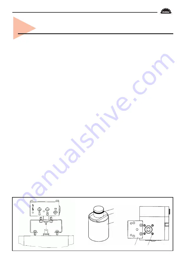
P4 and P5/EP5 mounts on to the actuator using either the ISO F05 holes 4 and a PMV ISO
mounting kit or by using the optional mounting adaptor and screws 5 to mount P5 on to
existing PMV mounting kits.
Proper alignment of the positioner spindle to the actuator shaft is very important since
improper alignment can cause excessive wear and friction to the positioner.
P5/EP5 only
The spindle/positioner shaft assembly allows for quick and simple spindle changes. To ensure
the proper connection, the spindle 3 has a spring clip 2 that must be properly installed. A
solid ”click” should be felt when assembling the two pieces insuring that the two flats 1 are
engaged into the positioner shaft groove.
The spindle can be removed, by inserting two screwdrivers under the two tapered surfaces
of the spindle and bending carefully. When the spring clip releases the spindle will eject.
4. Installation
5
4
2
1
3
P4/P5
P5/EP5
Summary of Contents for PMV EP5
Page 1: ...IOM Instructions P4 P5 EP5 alve Control System ...
Page 11: ...11 X Port plugged C1 C2 S C1 C2 S C1 C2 S I I I Direct function ...
Page 27: ...27 Dimensional drawing P4 ...
Page 30: ...30 Spare parts P5 EP5 84 ...
Page 32: ...32 84 Spare parts P5 EP5 ...
Page 34: ...34 18 Certificates Cenelec Atex black label ...
Page 35: ...35 Cenelec Atex black label ...
Page 36: ...36 ...
Page 37: ...37 Cenelec Atex white label ...
Page 39: ...FM White label ...
Page 40: ...CSA White label ...
Page 41: ......


