background image

M-200 AND M-600 APPLIANCE HARDWARE REFERENCE   |   Before You Begin   

9

©

 2018 Palo Alto Networks, Inc.

Product Safety Warnings

To avoid personal injury or death for yourself and others and to avoid damage to your Palo Alto Networks

hardware, be sure you understand and prepare for the following warnings before you install or service the

hardware. You will also see warning messages throughout the hardware reference where potential hazards

exist.

All Palo Alto Networks products with laser-based optical interfaces comply with 21 CFR
1040.10 and 1040.11.

The following safety warnings apply to all Palo Alto Networks firewalls and appliances, unless a specific

hardware model is specified.
• When installing or servicing a Palo Alto Networks firewall or appliance hardware component that has

exposed circuits, ensure that you wear an electrostatic discharge (ESD) strap. Before handling the

component, make sure the metal contact on the wrist strap is touching your skin and that the other end

of the strap is connected to earth ground.

French Translation:

 Lorsque vous installez ou que vous intervenez sur un composant matériel de

pare-feu ou de dispositif Palo Alto Networks qui présente des circuits exposés, veillez à porter un

bracelet antistatique. Avant de manipuler le composant, vérifiez que le contact métallique du bracelet

antistatique est en contact avec votre peau et que l’autre extrémité du bracelet est raccordée à la terre.

• Use grounded and shielded Ethernet cables to ensure agency compliance with electromagnetic

compliance (EMC) regulations.

French Translation:

 D es câbles Ethernet blindés reliés à la terre doivent être utilisés pour garantir la

conformité de l'organisme aux émissions électromagnétiques (CEM).

• (

PA-220 firewalls only

) The PA-220 firewall meets the requirements of IEC 61000-4-5 surge immunity

test. To prevent damage from electrical surges on Ethernet ports, we recommend that you use an

Ethernet surge protection device with the following specifications:
• Rated for Gigabit Ethernet up to category 5E and minimum 1Gbps.
• Protection provided on all eight signal leads.
• Both line-to-line and line-to-ground/shield are provided.
• Protection device must be connected to earth ground and use shielded category 5E or higher

Ethernet cable.

Technical Specifications:

• Protective circuit complies with IEC test classifications B2, C1, C2, C3, and D1.
• Normal discharge current (core to earth ground) is 2kA per signal pair.
• Normal discharge current (core to core) is 100A.
• Total discharge current is 10kA.

French Translation:

 (

PA-220 uniquement

) Les pare-feux PA-220 sont conformes aux exigences du test

d’immunité aux surtensions IEC 61000-4-5. Pour éviter les dommages résultant de surtension électrique

sur les ports Ethernet, il est recommandé d’utiliser un dispositif de protection contre les surtensions aux

caractéristiques suivantes:
• Gigabit Ethernet jusqu’à la catégorie 5E, débit 1 Go/s minimum.
• Protection sur les huit câbles signal.
• Le blindage et la mise à la terre “ligne à ligne” et “ligne à la terre” sont fournis.
• Le dispositif de protection doit être raccordé à la terre et un câble Ethernet blindé de catégorie 5E ou

supérieure doit être utilisé.

Caractéristiques techniques:

Summary of Contents for M-200

Page 1: ...M 200 and M 600 Appliance Hardware Reference paloaltonetworks com documentation...

Page 2: ...h for a specific topic go to our search page www paloaltonetworks com documentation document search html Have feedback or questions for us Leave a comment on any page in the portal or write to us at d...

Page 3: ...in a 19 Equipment Rack 30 Connect Power to an M 200 or M 600 Appliance 33 Connect AC Power to an M 200 or M 600 Appliance 35 Service an M 200 or M 600 Appliance 37 Replace an M 200 or M 600 Drive 39 R...

Page 4: ...iv TABLE OF CONTENTS...

Page 5: ...u install or service a Palo Alto Networks next generation firewall or appliance The following topics apply to all Palo Alto Networks firewalls and appliances except where noted Tamper Proof Statement...

Page 6: ...6 M 200 AND M 600 APPLIANCE HARDWARE REFERENCE Before You Begin 2018 Palo Alto Networks Inc...

Page 7: ...The tracking number provided to you electronically when ordering the product matches the tracking number that is physically labeled on the box or crate The integrity of the tamper proof tape used to...

Page 8: ...LIANCE HARDWARE REFERENCE Before You Begin 2018 Palo Alto Networks Inc Third Party Component Support Before you consider installing third party hardware read the Palo Alto Networks Third Party Compone...

Page 9: ...agency compliance with electromagnetic compliance EMC regulations French Translation D es c bles Ethernet blind s reli s la terre doivent tre utilis s pour garantir la conformit de l organisme aux mis...

Page 10: ...ewall is powered on but you must replace it within 45 seconds and you can only replace one fan tray at a time to prevent the thermal protection circuit from shutting down the firewall French Translati...

Page 11: ...granted only to craft service personnel using a special tool lock and key or other means of security and that is controlled by the authority responsible for the location French Translation Tous les pa...

Page 12: ...12 M 200 AND M 600 APPLIANCE HARDWARE REFERENCE Before You Begin...

Page 13: ...nt mode Panorama Management only mode Panorama Log Collector mode or PAN DB Private Cloud mode First Supported Software Release Panorama 8 1 The following topics describe the hardware features of the...

Page 14: ...14 M 200 AND M 600 APPLIANCE HARDWARE REFERENCE M 200 and M 600 Appliance Overview 2018 Palo Alto Networks Inc...

Page 15: ...e to help you locate the appliance when you move between opposite sides of the equipment rack Push the UID button again to deactivate these LEDs 3 System information overheat and UID LED Solid red An...

Page 16: ...must disconnect the AC power cords from both power supplies 9 Hard disk drives HDDs Disk drive bays and HDDs used for log storage By default the M 200 ships with four HDDs installed in drive bays A1 A...

Page 17: ...top of the appliance Upper left Management MGT port used for managing the appliance and for data traffic Upper right Ethernet1 1 Lower left Ethernet1 2 Lower right Ethernet1 3 For information on conf...

Page 18: ...nverter Use the following settings to configure your terminal emulation software to connect to the console port Data rate 9600 Data bits 8 Parity None Stop bits 1 Flow control None 6 Unique Identifica...

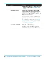
Page 19: ...n Press this button to reboot the appliance 3 Power LED Solid green indicates that the appliance is powered on 4 Power failure LED Solid red indicates that either a power supply failed or that there i...

Page 20: ...four additional RAID 1 pairs in the remaining drive bays C1 C2 D1 D2 E1 E2 and F1 F2 to increase log storage capacity Each pair of drives are in a RAID 1 configuration For example A1 A2 is a RAID 1 p...

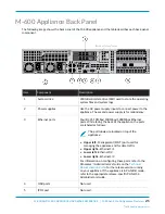
Page 21: ...is for redundancy 3 Ethernet ports Four RJ 45 10Mbps 100Mbps 1000Mbps Ethernet ports While facing the back of the appliance the ports are labeled as follows The port labels are located on top of the a...

Page 22: ...appliance when you move from the back to the front of the equipment rack where the appliance is installed When you push the UID button to enable the UID feature both the front panel System informatio...

Page 23: ...HARDWARE REFERENCE M 200 and M 600 Appliance Overview 23 2018 Palo Alto Networks Inc Item Component Description appliance If the appliance is in PAN DB mode refer to the appropriate release specific P...

Page 24: ...appliance has two additional SFP port LEDs For information on interpreting the front panel system LEDs see M 200 Appliance Front Panel or M 600 Appliance Front Panel descriptions LED Description RJ 4...

Page 25: ...in an Equipment Rack The M 200 and M 600 appliances ship with a four post rack kit for installation in a 19 four post equipment rack Install the M 200 Appliance in a 19 Equipment Rack Install the M 6...

Page 26: ...26 M 200 AND M 600 APPLIANCE HARDWARE REFERENCE Install M 200 or M 600 Appliance in an Equipment Rack 2018 Palo Alto Networks Inc...

Page 27: ...e the hooks Secure the back inner rails using two M4 screws for each rail and secure the front inner rails using one M4 screw for each rail The inner rails also use pressure lock clips that lock the r...

Page 28: ...rails in to the outer rack mount rails until the appliance stops about halfway in to the rack Push the inner rail release clips on each side of the two rails push the left clip up and the right clip...

Page 29: ...00 Appliance in an Equipment Rack 29 2018 Palo Alto Networks Inc STEP 4 Secure the front of the appliance to the rack by turning the front thumb screws on each rail clockwise until tight Secure the ba...

Page 30: ...e appliance to engage the hooks Secure the back part of each rail to the appliance using one M4 screw for each rail The inner rails also use a pressure lock clip one on each rail that locks the rails...

Page 31: ...ck by sliding the inner rails in to the outer rack mount rails until the appliance stops about halfway in to the rack Push the inner rail release clips on each side of the two rails to release the app...

Page 32: ...M 600 APPLIANCE HARDWARE REFERENCE Install M 200 or M 600 Appliance in an Equipment Rack STEP 4 Secure the front of the appliance to the rack by turning the front thumb screws on each rail clockwise...

Page 33: ...M 200 and M 600 appliances have two AC power supplies the second power supply is for redundancy For details on power requirements and power consumption see M 200 and M 600 Electrical Specifications C...

Page 34: ...34 M 200 AND M 600 APPLIANCE HARDWARE REFERENCE Connect Power to an M 200 or M 600 Appliance 2018 Palo Alto Networks Inc...

Page 35: ...orks hardware or the data that resides on the hardware read the Product Safety Warnings STEP 1 Plug two AC power cables provided in to grounded wall outlets Connect the second power cord through a dif...

Page 36: ...36 M 200 AND M 600 APPLIANCE HARDWARE REFERENCE Connect Power to an M 200 or M 600 Appliance...

Page 37: ...cribe how to replace serviceable components on an M 200 or M 600 appliance For information on interpreting the front panel and back panel LEDs see M 200 and M 600 Appliance Overview Replace an M 200 o...

Page 38: ...38 M 200 AND M 600 APPLIANCE HARDWARE REFERENCE Service an M 200 or M 600 Appliance 2018 Palo Alto Networks Inc...

Page 39: ...M 200 appliance is located on the front panel of the appliance see M 200 Appliance Front Panel and the system drive on the M 600 appliance is located on the back panel of the appliance see M 600 Appl...

Page 40: ...the MGT port on the appliance STEP 7 Change the IP address on your computer to an address in the 192 168 1 0 24 network such as 192 168 1 2 STEP 8 From a web browser go to https 192 168 1 1 and when p...

Page 41: ...A2 array can both be model ST91000640NS and the drives in the B1 B2 array can both be model ST1000NX0423 The following procedure describes how to replace a log drive on an M 200 or M 600 appliance tha...

Page 42: ...until it is fully open 2 Slide the drive carrier in to the drive bay on the appliance until it is about 1 4 from being fully inserted You can do this by pressing the ejector button on the carrier whi...

Page 43: ...replacement drive In this example run the following command to copy the data from drive A1 to drive A2 admin hostname request system raid copy from A1 to A2 4 Continue to view RAID status by periodic...

Page 44: ...200 AND M 600 APPLIANCE HARDWARE REFERENCE Service an M 200 or M 600 Appliance 2018 Palo Alto Networks Inc status active sync Disk id A2 Present model ST8000NM0055 1RM size 7630885 MB status active s...

Page 45: ...is a failure the LED turns solid yellow or turns off The front panel system information LED also blinks red STEP 2 Disconnect the power cord from the failed power supply STEP 3 Grasp the handle on th...

Page 46: ...46 M 200 AND M 600 APPLIANCE HARDWARE REFERENCE Service an M 200 or M 600 Appliance...

Page 47: ...600 appliance hardware specifications For feature capacity and performance information refer to the Panorama Datasheet M 200 and M 600 Physical Specifications M 200 and M 600 Electrical Specifications...

Page 48: ...48 M 200 AND M 600 APPLIANCE HARDWARE REFERENCE M 200 and M 600 Appliance Specifications 2018 Palo Alto Networks Inc...

Page 49: ...al specifications Specification Value Rack units U and dimensions M 200 appliance Rack unit 1U Dimensions 1 7 H x 29 D x 17 2 W 4 32cm H x 73 67cm D x 43 69cm W M 600 appliance Rack unit 2U Dimensions...

Page 50: ...fications Specification Value Power Supplies M 200 and M 600 appliances Two 750W AC power supplies the second power supply is for redundancy Input voltage and frequency M 200 and M 600 appliance 100 2...

Page 51: ...ting temperature M 200 and M 600 appliance 40 F to 140 F 40 C to 60 C Humidity tolerance M 200 and M 600 appliance Operating relative humidity non condensing 8 to 90 Non operating relative humidity no...

Page 52: ...600 Appliance Specifications M 200 and M 600 Miscellaneous Specifications The following table describes M 200 and M 600 appliance miscellaneous specifications Specification Value Mean time between fai...

Page 53: ...ply with the laws and regulations in each country where there are requirements applicable to our products Our products meet standards for product safety and electromagnetic compatibility when used for...

Page 54: ...54 M 200 AND M 600 APPLIANCE HARDWARE REFERENCE M 200 and M 600 Appliance Hardware Compliance Statements 2018 Palo Alto Networks Inc...

Page 55: ...mmunications However there is no guarantee that interference will not occur in a particular installation If this equipment does cause harmful interference to radio or television reception which can be...

Page 56: ...56 M 200 AND M 600 APPLIANCE HARDWARE REFERENCE M 200 and M 600 Appliance Hardware Compliance Statements...

Reviews: