background image

28

 • 

Palo Alto Networks

Avoid obstructing the air vents on the M-100 or pushing objects into the openings. This 
could lead to fire or electric shock.

Follow installation instructions carefully.

Do not attempt to service the equipment yourself. 

You should operate this equipment from the type of external power source indicated on 
the electrical ratings label.

Wait 30 seconds after turning off the equipment before removing a component from the 
system or disconnecting a peripheral device from the M-100.

Always leave at least 4 inches (10.2cm) of physical clearance on all vented sides of the M-
100. This permits the airflow required for proper ventilation.

Avoid placing equipment too close together such that it is subject to re-circulated (pre-
heated) air. Avoid placing equipment too close to an appliance or exhaust vent.

Ensure that cables are connected to the M-100 without stress and that nothing rests on the 
cables.

If the equipment is located in a rack, move it with caution. Ensure that all casters and/or 
stabilizers are firmly connected. While moving the equipment, avoid uneven surfaces and 
sudden stops.

Do not place other equipment, monitors, or other devices on top of the M-100.

To protect the M-100 from fluctuations in electrical power, use a surge suppressor, line 
conditioner or uninterruptible power supply (UPS).

Slide rail mounted equipment is not to be used as a shelf or a work space.

Elevated Operating Ambient – If the M-100 is installed in a closed or multi-unit rack 
assembly, the operating ambient temperature in the rack environment may be greater 
than the room ambient temperature. Therefore, consideration should be given to the 
maximum operating temperature specified in “Environmental Specifications” on page 24.

Reduced Air Flow – Installation of the M-100 in a rack should be such that the amount of 
air flow required for safe operation is not compromised.

Mechanical Loading – Mounting of the M-100 in the rack should not create a hazardous 
condition from uneven mechanical loading.

Circuit Overloading – Connection of the equipment to the supply circuit should not create 
an overloaded situation. Pay close attention to equipment nameplate ratings.

CAUTION

To prevent hardware damage or loss of data, observe the following precautions:

CAUTION

Please observe the following additional precautions for rack-mounted systems:

Summary of Contents for M-100

Page 1: ...M 100 Appliance Hardware Reference Guide...

Page 2: ...onetworks com documentation For access to the knowledge base complete documentation set discussion forums and videos refer to https live paloaltonetworks com For information on support programs to man...

Page 3: ...Installation 10 Connecting Cables to the Device 15 Connecting Power 16 Chapter 3 Service the Hardware 17 Cautions and Warnings 17 Replace an M 100 Appliance Disk Drive 18 Interpreting the Port LEDs 2...

Page 4: ...4 Table of Contents Palo Alto Networks Appendix A General Safety Information 27 Other Regulatory Information 29...

Page 5: ...ection for Palo Alto Networks firewalls This is the default mode Log Collector mode Functions as a dedicated Log Collector which either an M 100 or M 500 appliance in Panorama mode or a Panorama virtu...

Page 6: ...d indicates a system error 3 Internal HDD Activity Blinks if there is disk drive activity 4 LAN Activity Blinks if there is network activity 5 UID Button LED The Unique Identification UID feature is a...

Page 7: ...r to log collector communication For information on configuring this port for Panorama services refer to the Panorama Administrator s Guide on the Technical Documentation Portal for the release that t...

Page 8: ...10 100 1000 Ethernet port ethernet1 3 For information on configuring this port refer to the Panorama Administrator s Guide on the Technical Documentation Portal for the release that the appliance is r...

Page 9: ...product The tracking number provided to you electronically when ordering the product matches the tracking number that is physically labeled on the box The integrity of the tamper proof tape used to s...

Page 10: ...ck mounted device does not cause hazardous conditions due to uneven mechanical loading Circuit overloading Ensure that the circuit that supplies power to the device is sufficiently rated to avoid circ...

Page 11: ...nstalling the Hardware 11 Equipment Rack Installation Figure 3 Attaching the Inner Rail to the M 100 1 2 2 Attach the inner rail on both sides of the M 100 Press the latch to disconnect the inner rail...

Page 12: ...f this is a 4 post rack install continue to Step 3 If this is a 2 post install attached the 2 post brackets to the outer rail as shown in Figure 4 Figure 4 Attaching the 2 post Bracket for 2 post Rack...

Page 13: ...install will use the two outer brackets Both install methods are shown in Figure 5 Figure 5 Installing the Outer Rail on a 2 post and 4 post Rack Note If you are using a non threaded rack install the...

Page 14: ...that is now mounted on the rack and slide the appliance inward until it stops Simultaneously press the release latches on each side of the inner rail to allow the inner rail to completely slide into...

Page 15: ...and Figure 7 Tightening the Thumb Screws on the M 100 Connecting Cables to the Device Figure 8 shows the front M 100 cable connections Refer to Table 1 for descriptions of the front panel interfaces a...

Page 16: ...ting Power 16 Installing the Hardware Palo Alto Networks Connecting Power To power the M 100 attach a power cable to the device and plug it into a grounded wall outlet The device will power on automat...

Page 17: ...Warnings in the next section Replace an M 100 Appliance Disk Drive on page 18 Interpreting the Port LEDs on page 22 Cautions and Warnings CAUTION Disconnect all power cords before servicing the M 100...

Page 18: ...g output shows that disk drive A2 failed and the drive model is ST91000640NS Disk Pair A Available Status clean degraded Disk id A1 Present model ST91000640NS size 953869 MB status active sync Disk id...

Page 19: ...Install an M 100 Appliance Disk Drive Carrier 5 Remove the replacement drive from the packaging and compare the drive model written on the label with the drive model of the failed drive Proceed as fol...

Page 20: ...nd both drives show the status active sync To view RAID status run the following command admin M 100 show system raid detail The following output shows that the RAID 1 array is functioning properly Di...

Page 21: ...s that Disk Pair A is Available Disk Pair A Available Status clean degraded Disk id A1 Present model ST91000640NS size 953869 MB status not in use Disk id A2 Present model ST1000NX0423 size 953869 MB...

Page 22: ...rdware Palo Alto Networks Interpreting the Port LEDs Each Ethernet port on the M 100 has two LEDs Table 3 describes the LEDs Table 3 Port LEDs LED Description Left Shows green if there is a network li...

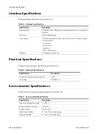
Page 23: ...ifications in the next section Interface Specifications on page 24 Electrical Specifications on page 24 Environmental Specifications on page 24 Physical Specifications Table 4 lists the physical speci...

Page 24: ...c Port 3 is reserved for future use MGT port 1 RJ 45 Ethernet port Console port 1 DB 9 serial port for connecting a serial console Use these settings Data rate 9600 Data bits 8 Parity none Stop bits 1...

Page 25: ...s section provides the compliance statement for the Voluntary Control Council for Interference by Information Technology Equipment VCCI which governs radio frequency emissions in Japan The following i...

Page 26: ...BSMI Statement 26 Compliance Statements Palo Alto Networks BSMI Statement...

Page 27: ...not exceed 80 percent of the ampere ratings limit for the extension cable or power strip The power supplies in the M 100 may produce high voltages and potential energy hazards By opening the cover of...

Page 28: ...ent avoid uneven surfaces and sudden stops Do not place other equipment monitors or other devices on top of the M 100 To protect the M 100 from fluctuations in electrical power use a surge suppressor...

Page 29: ...installed in a rack ensure that the system chassis is securely grounded to the rack cabinet frame Do not connect power to the system until grounding cables are connected Other Regulatory Information E...

Page 30: ...30 Palo Alto Networks...

Reviews: