36
PA-400 SERIES NEXT-GEN FIREWALL HARDWARE REFERENCE | Install the PA-400 Series Firewall
©
2021 Palo Alto Networks, Inc.
STEP 10 |
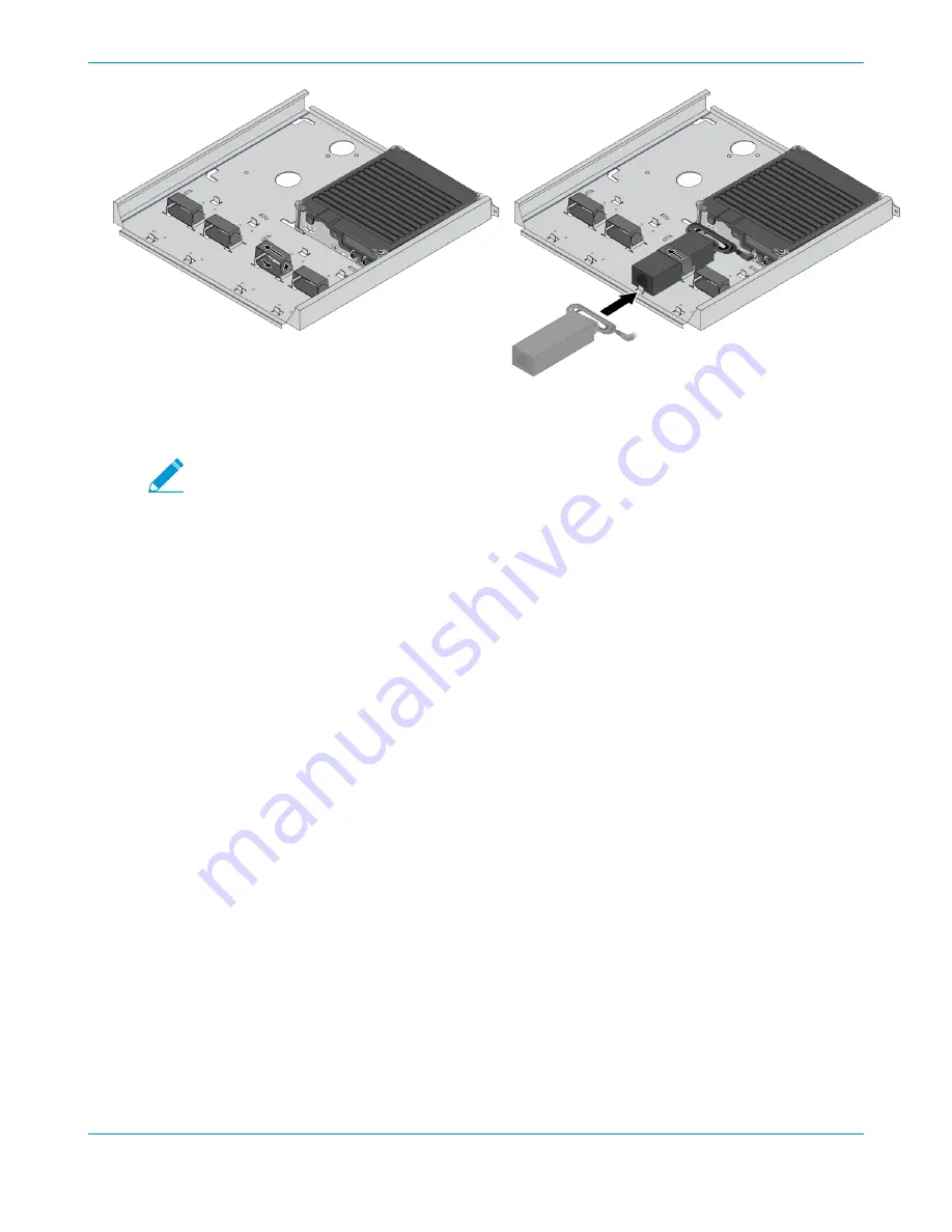
Plug the power supply connector into the back of the firewall. Using the provided tie-wraps,
bind and secure the power supply cable to the metal hooks in the mounting tray.
A redundant power supply can be mounted in the available position next to the primary
power supply.
STEP 11 |
(
If mounting a second firewall
) Repeat Steps 9 through 11 for the power supplies of the second
firewall.
STEP 12 |
Slide the mounting tray into the rails previously fixed to the equipment rack. Stop when the
front flange on the mounting tray is flush with the front of the rail.
STEP 13 |
Align the slotted holes in the mounting tray to the holes in the equipment frame. Secure the
mounting tray to the equipment frame on both sides using 3 screws each (not provided). The
screws must be compatible with your equipment frame.
Summary of Contents for PA-400 Series
Page 1: ...PA 400 Series Next Gen Firewall Hardware Reference paloaltonetworks com documentation...
Page 4: ...iv TABLE OF CONTENTS...
Page 14: ...14 PA 400 SERIES NEXT GEN FIREWALL HARDWARE REFERENCE Before You Begin...
Page 40: ...40 PA 400 SERIES NEXT GEN FIREWALL HARDWARE REFERENCE Install the PA 400 Series Firewall...


