background image

Palo Alto Networks

Compliance Statement  •  

33

May 29, 2015 - Palo Alto Networks COMPANY CONFIDENTIAL

Chapter 5 

Compliance Statement

NEBS Requirements

This section describes the Network Equipment Building System (NEBS) requirements for the PA-5000 
Series.

The PA-5000 Series is intended to be installed in a Network Telecommunication Facilities (Central 
Office) as part of a Common Bonding Network (CNB).

The battery return (BR) input terminals are considered to be an Isolated DC return (DC-1).

Bare conductors must be coated with an appropriate antioxidant compound before crimp 
connections are made. All un-plated connectors, braided strap, and buss bars must be brought to a 
bright finish and then coated with an antioxidant before they are connected.

Fastening hardware shall be compatible with he materials being joined ad shall preclude loosening, 
deterioration, and electrochemical corrosion of the hardware and the joined materials.

WARNING:  The intra-building ports of this equipment or subassembly is suitable for 
connection to intra-building or unexposed wiring or cabling only. The intra-building ports 
of equipment or subassembly must not be metallically connected to interface that connect 
to the OSP or it’s wiring. These interfaces are designed for use as intra-building interfaces 
only (Type 2 or 4 ports as described in GR-1089-CORE, issue 5) and require isolation 
from the exposed OSP cabling. The addition of primary protectors is not sufficient 
protection in order to connect these interfaces metallically to OSP wiring. INtra-building 
cabling must be shielded and grounded at both ends.

Summary of Contents for PA-5000 Series

Page 1: ...PA 5000 Series Hardware Reference Guide...

Page 2: ...ion set discussion forums and videos refer to https live paloaltonetworks com For contacting support for information on the support programs or to manage your account or devices refer to https support...

Page 3: ...ly 13 Chapter 3 Maintaining the Hardware 15 Cautions and Warnings 15 General Cautions Warnings 15 DC Power Related Cautions Warnings 16 Interpreting Status LEDs 18 Interpreting the Device LEDs 18 Inte...

Page 4: ...Chapter 4 Specifications 29 Physical Specifications 29 Interface Specifications 30 Electrical Specifications 30 Environmental Specifications 31 Chapter 5 Compliance Statement 33 NEBS Requirements 33 V...

Page 5: ...o Alto Networks COMPANY CONFIDENTIAL Chapter 1 Overview This chapter describes the features of the front and back panel of the PA 5000 Series firewall For more information refer to the following topic...

Page 6: ...rt One RJ 45 port to access the device management interfaces through an Ethernet interface Management console port One RJ 45 port for connecting a serial console High availability HA ports Two RJ 45 p...

Page 7: ...device management interfaces through an Ethernet interface Management console port One RJ 45 port for connecting a serial console High availability HA ports Two RJ 45 ports for high availability HA c...

Page 8: ...on The device is powered by plugging power cords into the power supplies Refer to Replacing a Power Supply on page 20 for instructions on replacing the power supplies Table 3 Back Panel Features Item...

Page 9: ...receipt of each product The tracking number provided to you electronically when ordering the product matches the tracking number that is physically labelled on the box or crate The integrity of the t...

Page 10: ...nt may be greater than the ambient room temperature Verify that the ambient temperature of the rack assembly meets the maximum rated ambient temperature requirements listed in Environmental Specificat...

Page 11: ...vel 4 Insert mounting screws into the aligned holes Tighten with a Phillips head screwdriver Connecting Cables to the Device Figure 5 shows the cable connections of the PA 5060 and PA 5050 Refer to Ta...

Page 12: ...e AC power connections for the PA 5000 Series Figure 7 Power Connection for the PA 5000 Series To power up the PA 5000 Series attach a power cable to each of the power supplies and plug each into a gr...

Page 13: ...Series Wind the power wires around the screws and tighten to secure The 48VDC connection is on the left and the 0VDC connection is on the right as labeled when facing the power supply Turn on the elec...

Page 14: ...Connecting Power 14 Installing the Hardware Palo Alto Networks...

Page 15: ...tatus LEDs on page 18 Replacing a Power Supply on page 20 Replacing a Hard Disk or Solid State Drive on page 22 Replacing the Fan Tray and Air Filter on page 25 Cautions and Warnings The following lis...

Page 16: ...ist strap must be implemented during the installation and maintenance of equipment CAUTION Shielded interface cables which are grounded must be used to ensure agency compliance with electromagnetic em...

Page 17: ...in restricted access areas only A restricted access area is where access can be gained only by service personnel through the use of a special tool lock and key or other means of security and is contr...

Page 18: ...the LED Dashboard LED State Description PWR POWER Green The device is powered Off Power is off STS STATUS Green The device is operating normally Yellow The device is booting up HA Green This device is...

Page 19: ...ower supply facing the back of the firewall is powered and active or is not installed Red The right power supply facing the back of the firewall is detected but not working The power supplies also hav...

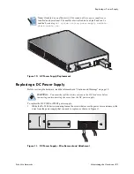
Page 20: ...tional The audible alert is disabled by default and can be enabled by running set system setting power supply audible alarm enable yes Replacing an AC Power Supply Before servicing the hardware read t...

Page 21: ...cure the power wires and remove the wires from the power supply that you need to replace as shown in Figure 11 Figure 11 DC Power Supply Wire Removal and Attachment Note If enabled an audible alert wi...

Page 22: ...The PA 5000 Series firewall has a bay that contains two 2 5 inch Serial Advanced Technology Attachment SATA hard disk drives or solid state drives SSD You must power down the firewall to replace eith...

Page 23: ...ews for the Drive Bay 4 Remove the metal plate that covers the disk drive bay 5 Push the button to the right of the drive to disengage the lever and release the drive Figure 14 Releasing a Drive 6 Gen...

Page 24: ...ting from standard to SSD drives The system will start to boot it will determine that the drives are different and then it will boot into maintenance mode with the reason Drive model mismatch You are...

Page 25: ...e to how automatic RAID selection works Replacing the Fan Tray and Air Filter To replace the fan tray and air filter 1 Identify the fan failure using the system log or fan LED 2 Make sure the new fan...

Page 26: ...nd slide the tray out The air filter slides out along with the fan tray Figure 18 Removing the Fan Tray and Air Filter 6 Slide the replacement fan tray in until it engages You must slide the new tray...

Page 27: ...t air filters from Palo Alto Networks or an authorized reseller You can replace the air filter without replacing the full fan tray It is not necessary to power down the firewall to replace the air fil...

Page 28: ...Replacing the Fan Tray and Air Filter 28 Maintaining the Hardware Palo Alto Networks...

Page 29: ...ions in the next section Interface Specifications on page 30 Electrical Specifications on page 30 Environmental Specifications on page 31 Physical Specifications Table 9 lists physical specifications...

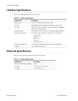
Page 30: ...A 5060 PA 5050 only Four 10 Gigabit Small Form Factor Pluggable SFP ports for network traffic Management ports One RJ 45 port to access the device CLI through an Ethernet interface Management console...

Page 31: ...5000 Series Table 12 Environmental Specifications Specification Description Operating temperature range 0 to 40 C Verified by NEBs compliance testing up to 50C Storage temperature range 20 to 70 C Hu...

Page 32: ...Environmental Specifications 32 Specifications Palo Alto Networks...

Page 33: ...ith an antioxidant before they are connected Fastening hardware shall be compatible with he materials being joined ad shall preclude loosening deterioration and electrochemical corrosion of the hardwa...

Page 34: ...Class A product In a domestic environment this product may cause radio interference in which case the user may be required to take corrective actions BSMI EMC Statement User warning This is a Class A...

Reviews: