6
Specifications
1-800-773- 7931 W W W .PALST AR.CO M
Front Panel Indicators and Controls
Metering
Dual movement cross needle power and frequency
compensated coupler
Controls
Input Tuning
Dual-stator differential capacitor (408 - 14 - 408) pF,
4.5 kV) with 6:1 precision vernier drive
Inductance
15 µH roller inductor; 12 ga. wire wound on steatite
ceramic core, silver plated bar/wheel. 10 µH fixed
toroid inductance, 14 ga. Teflon wire switched in and
out of circuit by front panel switch-controlled relay
Antenna Selector Switch
6 position: Coax 1 tuned and tuner bypass
Coax 2 tuned and tuner bypass
Bypass and balanced antenna
Power Range Switch
2 position 300 W /3000 W
Rear Panel Connectors
Coax 1
SO239 connector
Coax 2
SO239 connector
Bypass
SO239 connector
RF INPUT
SO239 connector
Balanced Line
Dual High Voltage Nylon66
TM
terminal post
End –Fed Wire
Dual High Voltage Nylon66
TM
terminal post
12 VDC Input
Adaptor for meter light 2.1 mm con. (center positive)
Other
Frequency Coverage
1.8 — 54 MHz
Power Maximum
1200 W PEP SSB; 800 W CW
Impedance Range
20 to 1500
Ω
160 m to 6 m (assuming resistive
load) Reduce power for lower Z range
Balanced Output
4:1 current balun
Dimensions
5.3”H x 12.25”W x 13”D (incl. terminals)
Weight
8 lbs.
Materials
Chassis and top cover is 11 ga. (.090) aluminum
that has been chem.-film treated in gold color. Front
Panel powder coated and epoxy screened.
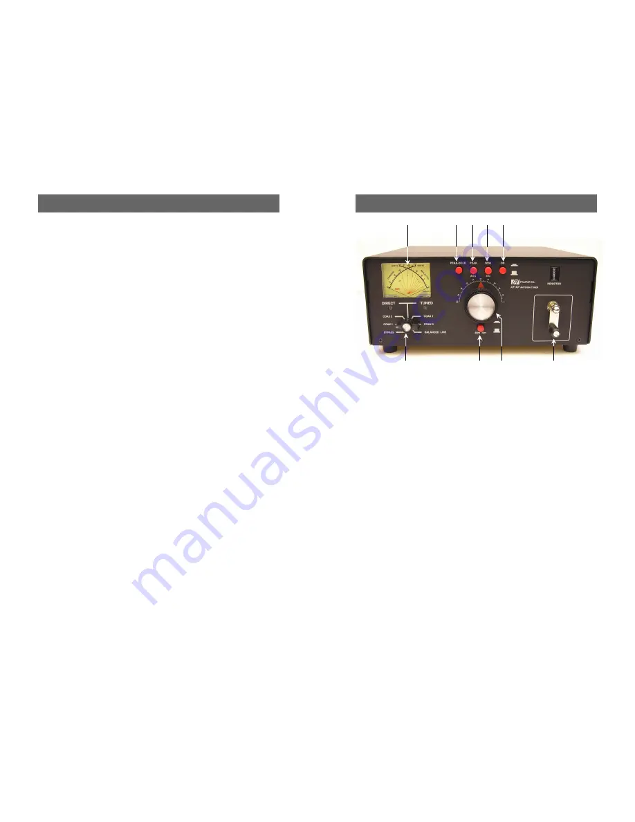
Front Panel Description
11
1-800-773- 7931 W W W .PALST AR.CO M
1. POWER/SWR METER
Dual needle
meter displays FORWARD and RE-
FLECTED power in watts. SWR is meas-
ured where the two needles intersect on
the red scale.
2. PEAK HOLD
Select to read Peak Hold
on the SWR meter.
3. PEAK
Selects between PEAK and AVER-
AGE Power metering display.
4. RANGE
Two-position switch selects the
range of FORWARD and REFLECTED
power displayed on the power meter.
When the RANGE button is OUT, the
FORWARD meter scale reads 300 watts
full scale and the REFLECTED meter scale
reads 60 watts full scale. When the RANGE
button is IN, the FORWARD meter scale
reads 3000 watts full scale and the RE-
FLECTED meter scale reads 600 watts full
scale.
5. POWER
Select to turn on the backlight
in the meter and enable Peak, Peak Hold,
and 160 Meter functions. The jack on the
back panel must be supplied with 12 VDC
for this to function.
6. INDUCTOR
15
µ
H continuously vari-
able ceramic roller inductor driven by a
crank handle. Coupled to the crank handle
is a gear-driven precision mechanical
counter.
7. TUNE
Continuously adjustable
differential capacitor.
8. 160 METER SWITCH
Pushing this
button to the IN position switches in extra
inductance for the 160 Meter Band. The
button should be in the OUT position for
use on all other bands — 80 through 6
Meters.
9. DIRECT-TUNED MODE SWITCH
Six-position rotary switch selects an output
coaxial connector with direct mode which
bypasses the tuner and tuned position
which passes antenna through the tuner
components.
a. DIRECT BYPASS selects BYPASS COAX
connector, bypassing the impedance matching
circuit but providing SWR, FORWARD and RE-
FLECTED meter readings.
b. DIRECT COAX 1 selects COAX 1 connec-
tor, bypassing the tuner matching circuit but
providing SWR, FORWARD and REFLECTED
meter readings.
c. DIRECT COAX 2 selects COAX 2 connec-
tor, bypassing the tuner matching circuit but
providing SWR, FORWARD and REFLECTED
meter readings.
d. TUNED COAX 1 selects COAX 1 connec-
tor through the impedance matching T circuit.
e. TUNED COAX 2 selects COAX 2 connec-
tor through the tuner matching T circuit.
f. BALANCED OUT selects the balanced and
End Fed Wire output connectors located after the
impedance matching circuit.
1
2
3
6
7
8
4
5
9


