12 Operating Your AT5K
Before Operating
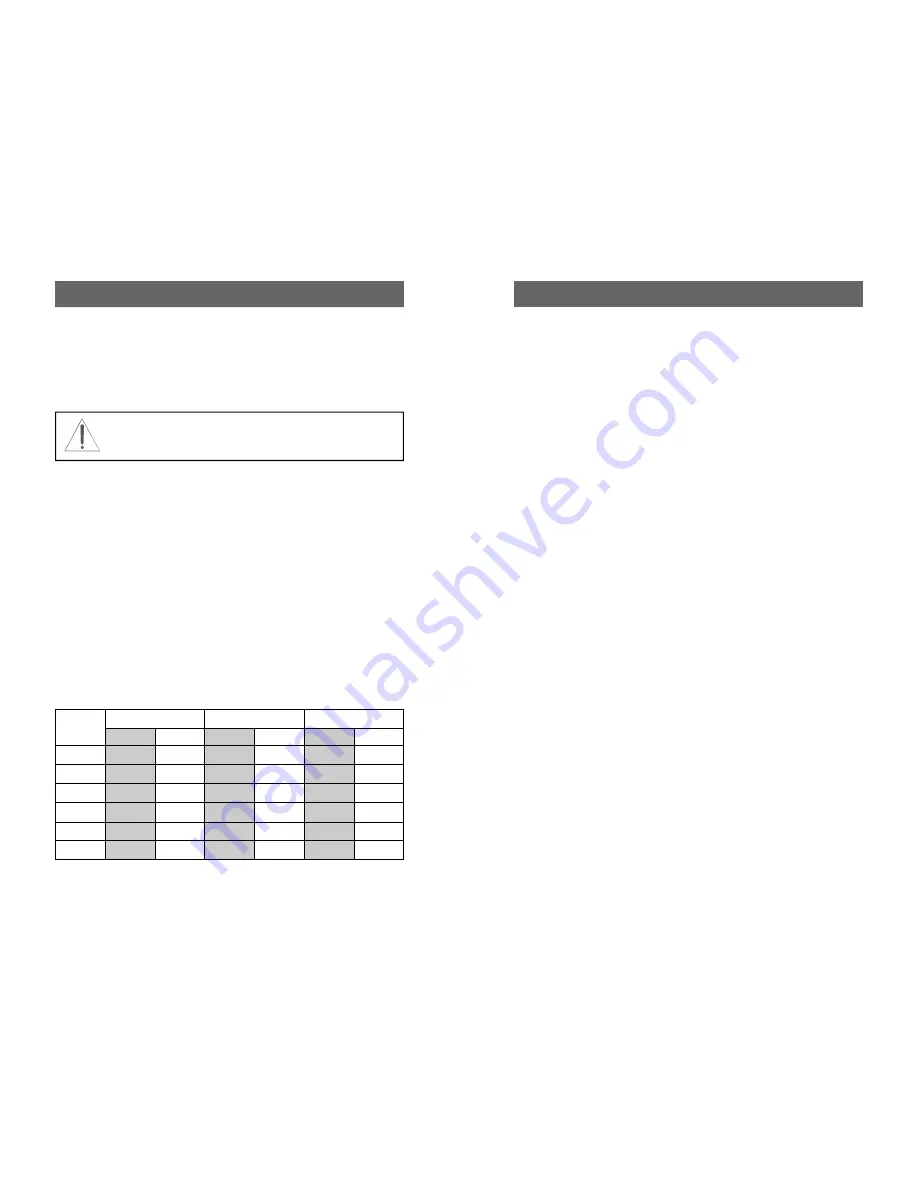
1. To avoid possible damage to the AT5K set INPUT, OUTPUT, INDUCTOR,
and POWER RANGE switches as outlined in the chart before applying trans-
mitter power.
2. Begin tuning with your transmitter/lamp into the tuner set at a low output
power setting (50-150 Watts).
Tuning
1. Select the band and frequency of desired operation.
2. Set TUNE and INDUCTOR controls to the suggested setting before applying
transmitter power (see chart). Actual settings will vary from antenna to an-
tenna.
3. Set your transmitter/amplifier to a low power output (100-150 watts). If your
transmitter/amplifier combination has a LOW POWER position, select that
position to obtain the 100-150 watts for the initial tune-up.
4. Preset the INPUT, OUTPUT, and INDUCTOR values shown in the chart
supplied for each band or on the label on the front panel. Select the type of
antenna feed you require (BALANCED or COAX) with the pushbutton on
the front panel. Note: BALANCED shows red LED.
5. Set the POWER RANGE switch to 300 W (with POWER range switch meter
button out).
6. Set the OUTPUT SELECTOR switch to the position matching your antenna
connection. To tune your antenna, the switch selection must be set to:
COAX 1 TUNED, COAX 2 TUNED or WIRE (BALANCED ANTENNA).
Selecting COAX 1 DIRECT, COAX 2 DIRECT or BYPASS bypasses the tun-
ing selection.
WARNING: DO NOT OPERATE THE AT5K
WITH THE COVER OFF.
BAND
INPUT
OUPUT
INDUCTOR
SUGGESTED
ACTUAL
SUGGESTED
ACTUAL
SUGGESTED
ACTUAL
160 M
32
32
20
80 M
31
33
148
40 M
28
35
202
20 M
34
32
208
15 M
44
14
218
10 M
100
10
229
Note: end of the roller (max turns clockwise) is 229 = minimum in-
ductance. Maximum inductance is ZERO (0) on the mechanical
counter.
Front Panel Description 9
6. POWER ON
The IN position provides power for the
Peak and Peak Hold metering circuit, relay and
meter illumination.
7. INDUCTOR
28 µH continuously variable ceramic
roller inductor driven by a crank handle. Coupled to
the crank handle is a gear-driven precision me-
chanical counter. (Max.= 0; Min. = 229)
8. OUTPUT
Continuously adjustable output capacitor.
Min. capacitance=0. Max capacitance = 100.
9. DIRECT-TUNED MODE SWITCH
Six-position rotary
switch selects an output coaxial connector.
a. DIRECT BYPASS
selects BYPASS COAX connec-
tor bypassing the impedance matching circuit but
providing SWR, FORWARD and REFLECTED
power meter readings.
b. DIRECT COAX 1
selects COAX 1 connector by-
passing the tuner matching circuit but providing
SWR, FORWARD and REFLECTED meter read-
ings.
c. DIRECT COAX 2
selects COAX 2 connector by-
passing the tuner matching circuit but providing
SWR, FORWARD and REFLECTED meter read-
ings.
d. TUNED COAX 1
selects COAX 1 connector
through the impedance matching T circuit.
e. TUNED COAX 2
selects COAX 2 connector
through the impedance matching T circuit.
f. TUNED BAL
selects the END FED WIRE connec-
tor through the impedance matching circuit. For
balanced antennas, the balanced coax switch (5)
must be IN.
10. INPUT
Continuously adjustable input capacitor.
Min. capacitance = 0. Max = 100.


