6
UNPACKING INSTRUCTIONS
Carefully remove your Commander VHF-144 from its shipping carton making sure there is
no damage evident from shipping. If there is any damage, notify the delivering shipper imme-
diately, fully describing the damage.
Do not destroy the packing material
, since it may be reusable later, should you require
factory service, or need to transport the Amplifier for any other reason.
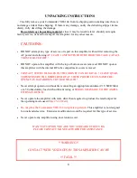
CAUTIONS:
•
DO NOT attempt any type of service or repair on this amplifier without first removing the
AC power and allowing
AT LEAST 10 MINUTES FOR THE HIGH VOLTAGE CAPACI-
TORS TO BLEED OFF !
•
DO NOT operate this amplifier with the top or bottom covers removed. DO NOT operate
this amplifier with the internal RF tube compartment covers removed.
•
CONTACT WITH VOLTAGES IN THE CABINET CAN BE FATAL ! CLOSE QUAR-
TER EXPOSURE TO UNSHIELDED RF AT THESE POWER LEVELS AND FRE-
QUENCY IS HAZARDOUS TO YOUR HEALTH !
•
Never attempt operation without first connecting an appropriate antenna (2:1 VSWR Max)
or a 50 ohm dummy load with sufficient rating or
SERIOUS DAMAGE TO THE AMPLI-
FIER MAY RESULT.
•
Never operate the amplifier with more drive than required to produce the rated output for
the operating mode used (
Max 25-30 Watt
).
•
Do not place the Commander VHF-144 in repeater operation
. This amplifier is not designed
for unattended service. Extensive modification would be required for this type of service.
•
Never operate any amplifier using an extension cord.
IF ANY SITUATION YOU ARE NOT SURE ABOUT OCCURS,
PLEASE CONTACT MANUFACTURER FOR ASSISTANCE.
!! WARNING !!
CONTACT WITH VOLTAGES IN THIS AMPLIFIER CAN BE
!!! FATAL!!!
Summary of Contents for COMMANDER VHF-144
Page 12: ...12 Commander VHF 144 HV Power Supply...
Page 13: ...13 AC Mains and Step Start Board VHF 144 13 5VAC...
Page 14: ...14 Control and Metering Board VHF 144...
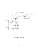
Page 15: ...15 RF Deck VHF 144...
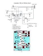
Page 16: ...16 Commander VHF 144 T R Relay Board...
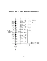
Page 17: ...17 Commander VHF 144 Voltage Doubler Power Supply Board...
Page 20: ...20 Meter Board Cathode Fuse...
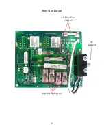
Page 21: ...21 Step Start Board AC Main Fuse 20A x 2 AC Interlock Step Start Relays x 4...
Page 22: ...22 Power Supply 470uF Capacitor 450 vdc x 8 HV Sense RF Output...
Page 23: ...23...


