8
INSTALLATION PREPARATION
The Commander VHF-144 is factory wired for operation from an 234VAC line
. Operation at
the full rated output should not be attempted unless the AC line is capable of supplying at least
15 amps of peak current. It is strongly recommended that you operate this amplifier from a
234VAC line.
Install an appropriate plug on the end of the power cord to mate with your wall receptacle.
If you change the operating voltage as described above, be sure to install the proper fuse.
The fuse is a type SFE, 20 Amp for 234 VAC & 200 VAC operation.
All Commander VHF-144 amplifiers manufactured for export are wired for 200 or 234VAC,
50 or 60 Hz, depending on the final destination. No plug is supplied with the AC line cord.
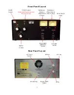
Location of your Commander VHF-144 requires that no equipment be placed directly
against the left side vent, as air expelled from the tube exhaust can become quite hot. Allow at
least 3 inches clearance on the side of the unit and between other equipment.
To switch from transmit to receive the Commander VHF-144 requires a contact closure or
keying circuit capable of sinking 15ma of positive voltage (12 VDC open circuit) to ground.
This connection is made to the RCA jack on the rear panel marked KEY. Read the manual that
came with your transceiver to determine the proper external connections. On some transceivers,
this is not provided, and an alternate circuit will be required. Always use shielded cable for
these connections.
Connect a good quality thru-line analog Wattmeter between the amplifier output jack and the
antenna or dummy load using RG8 or better coax.
Connect the exciter (transceiver) RF output to the amplifier input using 50 ohm coax.
Connect a ground lead, as short as possible, from earth ground to the Commander VHF-
144’s rear panel ground terminal.
!!CAUTION!!
BE SURE YOU HAVE REMOVED THE LINE CORD PLUG FROM YOUR WALL
SOCKET BEFORE REMOVING THE JUMPER COVER. IF YOU FAIL TO UNPLUG
YOUR AMPLIFIER, YOU WILL EXPOSE YOURSELF TO LETHAL VOLTAGES
.
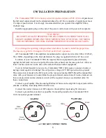
AC SOCKET CONNECTIONS
White
(Natural)
Green
(Ground)
Black
(230 VAC)
Black
White
Green
Amplifier
Wall Outlet
Summary of Contents for COMMANDER VHF-144
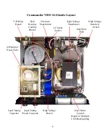
Page 12: ...12 Commander VHF 144 HV Power Supply...
Page 13: ...13 AC Mains and Step Start Board VHF 144 13 5VAC...
Page 14: ...14 Control and Metering Board VHF 144...
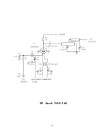
Page 15: ...15 RF Deck VHF 144...
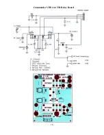
Page 16: ...16 Commander VHF 144 T R Relay Board...
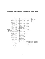
Page 17: ...17 Commander VHF 144 Voltage Doubler Power Supply Board...
Page 20: ...20 Meter Board Cathode Fuse...
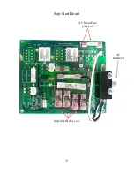
Page 21: ...21 Step Start Board AC Main Fuse 20A x 2 AC Interlock Step Start Relays x 4...
Page 22: ...22 Power Supply 470uF Capacitor 450 vdc x 8 HV Sense RF Output...
Page 23: ...23...


