9
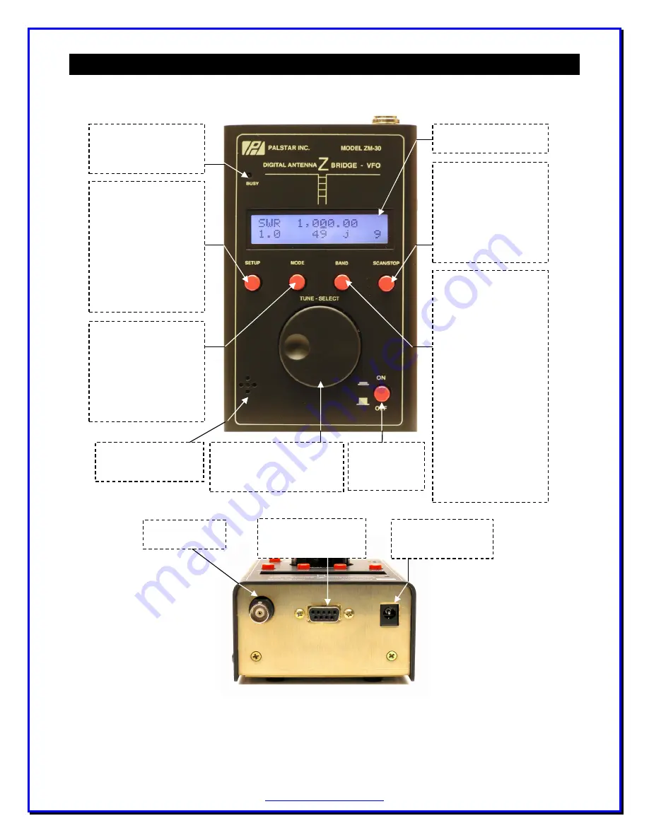
SETUP
Provides menu of user-
configurable settings and
functions:
- Custom Scan settings
- Audio tone
- Software Load
- Calibrate
- Debug Mode
- Power-Off time
- Backlight control
- View Settings
MODE
User can change the
ZM-30 to any of the 4
available operating
modes:
- Impedance (default)
- Capacitance
- Inductance
- VFO
BUSY Light
Turns on when scanning
and when saving user
settings.
External Power Jack
2.1mm jack, center
positive, 9-16V DC
RF Output Jack
BNC
BAND
User can select one of 14
pre-set bands, or enter
specific parameters for a
custom-set band to use
for the scan operation:
- 1-10 MHz
- 10-20 MHz
- 20-30 MHz
- 1-30 MHz
- 160m
- 80m
- 60m
- 40m
- 30m
- 20m
- 18m
- 15m
- 12m
- 10m
- Custom Band
SCAN
Pressing this control
initiates a scan of the
frequencies selected in
the BAND function. Scan
exits to Impedance mode
showing the resonant
point in the antenna
system.
Power Control
Push-hold to
turn unit on or
off.
Audible Tones
When enabled, tones
indicate value of SWR.
Dial
Main part of user interface,
used to select menu items and
frequency settings.
RS-232 Serial Port
Connect to PC when
loading new software.
TOP END VIEW
FRONT PANEL
LCD Display
2 lines x 16 characters
Summary of Contents for ZM-30
Page 1: ...ZM 30 Digital Antenna Analyzer Owner s Manual Firmware Level Version 6 0 ...
Page 5: ...5 0 1 F 0 9 0 9 1 1 2 0 0 0 0 5 1 0 1 0 0 7 7 G G B 9 7 7 7 7 1 7 7 7 7 F 7 7 4 F 7 7 0 5 ...
Page 25: ...25 ZM30 Menus ...
Page 26: ...26 ...
Page 27: ...27 ...
Page 28: ...28 ...
Page 36: ...36 Notes ...
Page 37: ...37 Notes ...


