© Pan Acoustics GmbH
Page 11 of 14
Assembly Manual
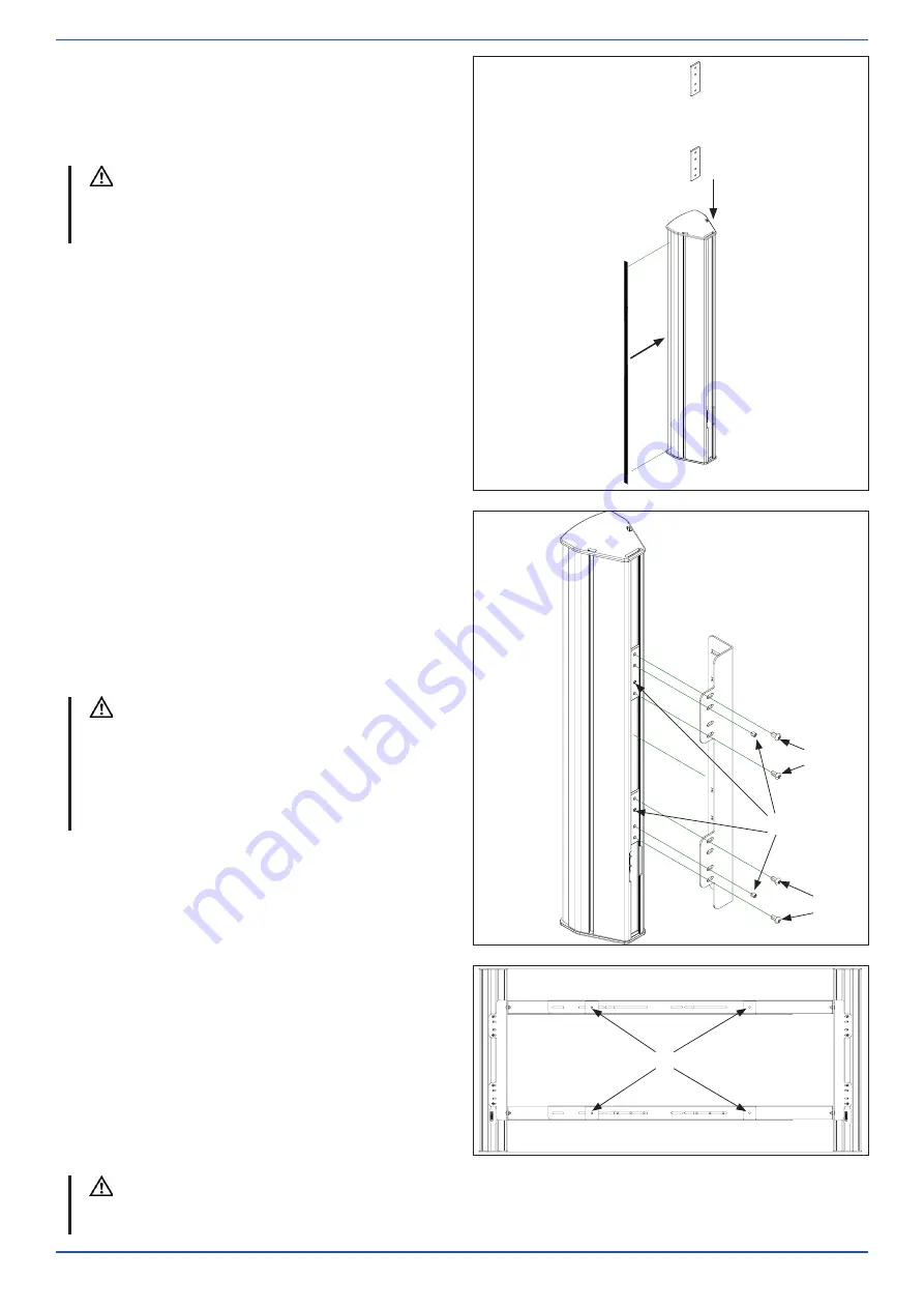
Step 4:
The loudspeakers must be prepared as shown
in the picture:
Insert 2 x slot nuts (G)
Stick on cellular rubber band (J)
Fit the cellular rubber band on the side of the
loudspeaker facing the display to close the
resulting gap.
NOTICE
J
G
Step 5:
The loudspeakers must be mounted on the VSM
/ VSM XL bracket V (B) as shown in the picture.
First position the slot nuts and fi x them with the
set screws (H) in the two middle holes so that
the screws (F) can be screwed into the slot nut
through the bracket (B).
H
F
F
Subsequent vertical and/or horizontal ad-
justment of the loudspeaker position is pos-
sible by slightly loosening the screws. The
loudspeaker must be secured against slip-
ping by suitable measures, e.g. by holding it.
NOTICE
B
Step 6:
Prior to mounting the VESA monitor mount, 4
spacers (I) must be positioned centred over
the VESA mounting points of the display.
For mounting the desired VESA monitor mount,
the assembly kit includes screws in various
sizes and lengths.
F
All screw connections must be checked for secure fi t and friction locking. The individual components must be
checked to ensure that they are form fi tting, and screw connections must be re-tightened where appropriate.
NOTICE


