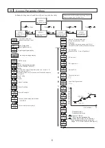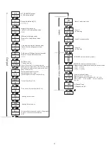
9. Access Parameter Menu
Schematic diagram of each level (how to switch
s)
level
*Return to level 0(operation setting level if
no pressing any key within 30sec
Operation set up
level
Press
Press
and
for 3sec
Press
Press
Press
Press
Press
Program parameter
setup level
and
and
and
and
and
Parameter control
setup level
Output calibration
parameter level
(
Manufacturer specialized)
Iutput calibration
parameter level
(
Manufacturer specialized)
Operation setup level
(general operation level
power ON
self-
diagnosis
self-diagnosis
(all lights turn on)
Input signal type display
Output percentage monitor
Only for MG904
、
MG907)
0:Stop
1:Run(when power off and then power on return to “0",
when running set”1")
2:Run(Not return to “0"when power off and then power on
,still as “2"
Auto Tuning
1:ON
2:None
Alarm 1 setting
Alarm 2 setting
Input signal range display
Lower limit
Upper limit
5s
5s
PV/SV value
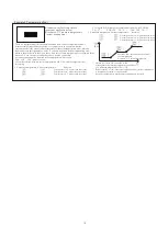
refer to Example1
Cold controlled proportional band
Cold control output cycle(s)
Control
Program setup level
(Engineer operation level)
Data lock
LCK=0001,only allow changes SV,RUN
LCK=0010,allow level0 process mofication
set input type
please refer to “5.Input Type Table”
Input filtering constant
M
e
a
s
u
re
m
e
n
t V
a
lu
e
PV1,off Set
Constant Value
Consumption Value
1.TM1=0,TM2=0
TM=3 none compensation
2.When TM1=USP,TS1 is constant
consumption(whole measurement
range
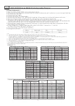
(refer to Example 3)
PV1,off Set
PV1 lower limit
PV1 upper limit
decimal Set
Temperature unit
0:
℃
1
:℉
5
0.0-50.0


