background image

6

USA & Canada (800) 472-5555  •  (707) 283-5900  •  Fax (707) 283-5901

5.

Windows will recognize your UPS as “New Hardware”.

6.

Insert the software disk into the computer’s drive.  The instal-

lation program should start automatically.  If the installation pro-
gram does not start automatically, open it manually with the
Window’s “Run” command. 

7.

Follow the on-screen instructions.

8.

Once the software is installed, remove the disk and restart

your computer.

For Windows 2000
1.

Click on Start, point to Settings then click Control Panel.

2.

Double-click on Power Options.

3.

On the UPS Tab, click Select.

4.

In the UPS Selection Dialog Box, under Manufacturers, 

click None. 

5.

Exit to the desktop.

6.

Shutdown the computer.

7.

Turn the UPS off and unplug it.

8.

Connect the serial interface cable to the UPS and an open 

serial port on the back of the computer. (Note: You must use 
the serial cable that was supplied with the unit).

9.

Plug the UPS into an AC outlet, turn the UPS on and start 

your computer. 

10.

Windows will recognize your UPS as “New Hardware”.

11.

Insert the software disk into the computer’s drive.  The

installation program should start automatically.  If the installation
program does not start automatically, open it manually with the
Window’s “Run” command.

12.

Follow the on-screen instructions.

13.

Once the software has finished installing, remove the disk

and restart your computer.

For Windows NT 4.0
1.

Click on Start, point to Settings then click Control Panel.

2.

Double-click on the UPS Icon.

3.

. Remove the check mark from the box labeled UPS is installed

on. 

4.

Click OK.

5.

Acknowledge the message that the UPS is in an unknown

state.

6.

Exit to the desktop.

7.

Shutdown your computer.

8.

Turn the UPS off and unplug it.

9.

Connect the serial interface cable to the UPS and an open seri-

al port on the back of the computer. (Note: You must use the
serial cable that was supplied with the unit).

10.

Plug the UPS into an AC outlet, turn the UPS on and then

start your computer. 

11.

Click on Start, point to Settings then click Control Panel.

12.

Double-click on Add/Remove Programs.

13.

Insert the software disk into the computer’s drive.  The

installation program should start automatically.  If the installation
program does not start automatically, open it manually with the
Window’s “Run” command.

14.

Click Install.

15.

Follow the on-screen instructions.

16.

Once the software is installed, remove the disk and restart

your computer.

When your computer restarts, the Home Cinema Power Control
software will appear on your screen for a few seconds, and then
minimize. It will appear as a blue and white battery icon located
in the system tray, near the clock.

Home Cinema Power Control Software 

(continued)

Summary of Contents for M1500-UPS

Page 1: ...ual POWER TEST MAX Home Cinema UPS Pure Sine Wave Intelligent Critical Load Control UNSAFE VOLTAGE LINE FAULT POWER ON AVR MODE BATTERY MODE BATTERY LEVEL LOAD LEVEL 1690 Corporate Circle Petaluma CA...

Page 2: ...tions pgs 7 8 9 10 Battery Features pgs 10 11 Diagnostics pg 11 Troubleshooting pg 12 Technical Specifications pg 12 RS232 Communications Protocol Command Set pgs 13 14 15 16 FCC Notice and Warranties...

Page 3: ...ife support equipment with any medical applications or patient care CAUTION The battery can energize hazardous live parts inside even when the AC input power is disconnected CAUTION To prevent the ris...

Page 4: ...nd does not service equipment with large electri cal demands e g refrigerator copier etc Avoid using exten sion cords If used the extension cord must be rated for 15 Amps 5 Press the power switch to t...

Page 5: ...nd the 3rd above 75 The 4th arrow will flash when the load is between 85 and 100 Battery Level Indicator This is a visual indication of the battery charge If battery capac ity is under 25 no indicator...

Page 6: ...th outputs The IR LED s will flash once per second during the delay time and will stop flashing after the IR code is output 2 If the delay settings are the same for both IR1 and IR2 the IR2 code will...

Page 7: ...me Cinema Power Control Software The M1500 UPS has one rear panel serial port that provides the ability to program special functions safely shutdown a home the ater PC HTPC or integrate the UPS with h...

Page 8: ...and 12 Follow the on screen instructions 13 Once the software has finished installing remove the disk and restart your computer For Windows NT 4 0 1 Click on Start point to Settings then click Control...

Page 9: ...own the HTPC during extended power fail ures This requires a permanent RS232 connection to the HTPC and having the Home Cinema Power Control software running in the background on the HTPC When a power...

Page 10: ...ds to be used exclusively for the UPS software 12 Time between power failure and shutdown For use with an HTPC This is the user controllable delay between when the power fails and the software starts...

Page 11: ...tes and times of any scheduled startups and shut downs 7 Delete Clears the selected item from the schedule 3 Turn Off Select the day date and time that you want the computer system to shutdown This is...

Page 12: ...the red run button The unit will cycle to battery mode and emit an audible beep With the software self test the unit will switch back to AC power automatically Battery Replacement Read and follow the...

Page 13: ...eps Rapid Beeps Long Beep Long Beep None Off None Condition Normal AVR Max boost 13 of input voltage for output regulation while input voltage is from 8 to 15 under nominal AVR Max boost 26 of input v...

Page 14: ..._____________________________Yes Maintenance free____________________________________________________________Yes Lead acid___________________________________________________________________Yes User re...

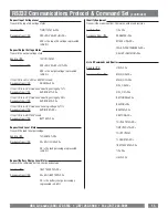
Page 15: ...outlets on and off to force a hard reboot of equipment Devices such as satellite receivers often crash and must be reset The following are commands made by the controller to the UPS AC INPUT BATTERY M...

Page 16: ...pace 20 Hex XX is a number between 25 and 60 represented in ASCII If XX is a valid number between 25 and 60 Action Assigns the battery threshold variable with the value XX Response from UPS BTHRESH SP...

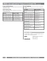
Page 17: ...is in AVR mode and bucking voltage by 11 Response from UPS AVRBUCK1 CR If the UPS is in BATTERY mode Response from UPS BATTERY CR Request Load Level Status Transmit the load level percentage Send to U...

Page 18: ...n AVR or BATTERY mode UPS is in AVR boosting 13 UPS is in AVR boosting 26 UPS is in AVR bucking 15 UPS is in BATTERY mode Battery charge falls below critical load threshold Input voltage exceeds high...

Page 19: ...e date of purchase that the unit shall be free of defects in design materi al or workmanship and Panamax will repair or replace any defective unit Upgrade Policy Valid only in the United states and Ca...

Page 20: ...1690 Corporate Circle Petaluma CA 94954 Tel 707 283 5900 Fax 707 283 5901 Email sales panamax com Web www panamax com 2005 Panamax INS0763 REV B 7 05...

Reviews: