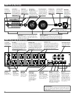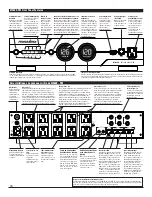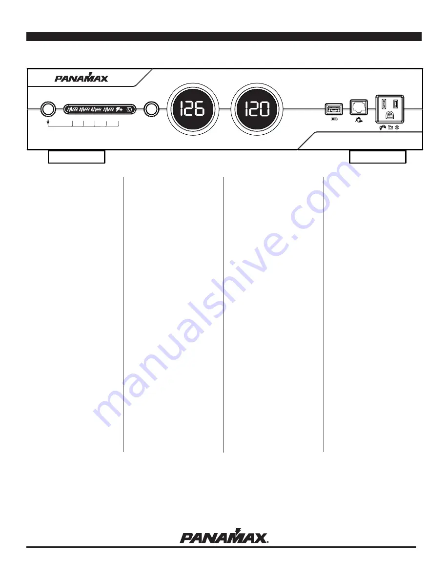
Key Features
Voltage Regulation
Regulates the output voltage on Banks 1-4 to
120 VAC ± 5 VAC. This is accomplished
through two boost stages and one buck stage
of voltage regulation. In Boost Stage 1 the
voltage is boosted in the 109-119V range,
while Boost Stage 2 boosts the voltage in the
100-109V range. The Buck Stage acts to
reduce voltage in the 125-136V range.
LiFT Technology EMI/RFI Noise Filtration :
Your audio/video components are constantly
being bombarded by electromagnetic interfer-
ence (EMI) and radio frequency interference
(RFI) through their AC power source. This
contaminated power can affect audio/video
equipment and will degrade the overall per-
formance of your entire system. Common
symptoms of contaminated power include
loss of picture detail, dull colors, pops, hiss-
es, hums and visual artifacts.
Automatic Over & Under Voltage Protection
(AVM):
Panamax's patent pending power monitoring
circuitry constantly monitors the AC line volt-
age for unsafe voltage conditions such as
momentary spikes or prolonged over-volt-
ages and under-voltages (brownouts). These
unsafe conditions pose a very dangerous
threat to all electronic equipment within the
home. If the MAX® 5400-PM senses an
unsafe power condition, it will automatically
disconnect your equipment from the power to
protect equipment from damage.Once the
voltage returns to a safe level, the M5400-PM
will automatically reconnect the power.
• When subjected to a 6,000V (open circuit
voltage) / 500A (short circuit current) surge,
the M5400-PM limits its voltage output to
less than 330V peak, UL's best rating.
• If the magnitude of the surge is greater than
the capacity of the surge protection compo-
nents, the M5400-PM's Protect or Disconnect
Circuitry will disconnect your equipment in
order to protect it. The M5400-PM will need
to be repaired or replaced by Panamax if this
occurs within the product’s 3 year warranty.
5 Isolated Outlet Banks
The M5400-PM is designed to provide noise
isolation between the outlet banks so that any
noise created by A/V components plugged
into the M5400-PM cannot contaminate the
power going to equipment plugged into the
other outlet banks of the M5400-PM.
Sequential Startup/Shutdown:
Complex audio/video systems may be sus-
ceptible to voltage transients generated inter-
nally at start-up/shutdown if all of the equip-
ment is powered on or off at the same time.
This can cause speaker “thumps” which are
not only annoying but can also damage the
speakers and/or trip product circuit breakers.
The M5400-PM is designed to eliminate these
transients by providing a “start-up” delay for
the High-Current outlets and a “shutdown”
delay for the Switched Outlet Banks. This
minimizes in-rush current issues by allowing
the components plugged into the Switched
Outlet Banks to power-up and stabilize before
any amplifiers and powered sub-woofers are
turned on. This sequence is reversed during
shutdown. The amplifiers and powered sub-
woofers turn off, their power supplies drain,
and then the equipment plugged into the
Switched Outlet Banks are turned off.
USB Charger:
The M5400-PM features a front panel con-
venience charger for mp3 players, cell
phones, video game controllers, and other
small electronics. NOTE: Some devices may
not be compatible with this USB charger.
Gaming LAN Port:
The M5400-PM features an easy-to-access
LAN port pass-thru from the rear panel to the
front panel. Perfect for online gaming.
Gaming Outlet:
The M5400-PM features a convenience outlet
located on the front panel. Perfect for gaming
systems and other electronics. 120VAC ±
6VAC
Voltage Sense Trigger:
The M5400-PM volt-
age sense trigger input uses a standard
3.5mm (1/8") mini-mono plug.
This feature provides an ON/OFF trigger for
the M5400-PM using a Direct Current voltage
signal. Many components such as pre-ampli-
fiers and receivers have a DC trigger built in,
and will transmit a constant power signal
when turned on and in use. The presence of
this power signal will turn on the M5400-
PM's switched outlets. When the source com-
ponent is turned off, the voltage trigger signal
is also turned off and the M5400-PM's shut-
down sequence is initiated. An AC Adapter of
the appropriate voltage plugged into a
switched outlet may also be used if a DC trig-
ger is not built in.
Cable/Satellite/Antenna TV signal protec-
tion
Coaxial protection circuits achieve optimum
signal quality from our new coaxial protectors
that have the smallest signal loss on the mar-
ket - less than 0.5 db of attenuation from 0
MHz to 2.2 GHz. Our upgraded coaxial pro-
tection has been specifically designed to vir-
tually eliminate signal loss. The clamping
level of 75V will meet the demands of both
cable and satellite voltage while minimizing
exposure to damaging spikes and surges.
Telephone Line Protection:
Digital video recorders and satellite TV
receivers require a telephone line connection
for TV show scheduling and/or Pay-Per-View
services. The M5400-PM also provides surge
protection for this line. One pair of RJ-11 tele-
phone jacks is provided for this. The circuitry
utilizes auto-resetting PTCRs and solidstate
SIDACtors for reliability and unsurpassed
protection. The clamping level of the M5400-
PM's telephone protector is 260 volts. This
will allow typical ring voltage (90-130VAC)
and operating battery voltage (-48DC) to pass
through the circuit and still protect the
modem in your satellite receiver from dam-
age.
LAN Protection:
Protection circuits for 10/100 baseT Ethernet
lines. Incoming LAN line MUST be plugged
into the LINE jack. Patch cord to the equip-
ment MUST be plugged into the EQUIP jacks.
1 LAN jack goes to the front panel output jack.
8 wire protection, 52V clamping.
Model:
M5400-PM
INS00815-E Rev. C 9/09
1
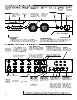
BANK 1 BANK 2 BANK 3 BANK 4 BANK 5
M5400-PM
VOLTAGE REGULATOR
METER LIGHTS
METER TOGGLE
VOLTAGE
REGULATION
VOLTAGE
REGULATION
VOLTAGE
REGULATION
VOLTAGE
REGULATION
HIGH
CURRENT
WIRING
OK
VOLTS IN
VOLTS OUT
CAUTION
– Do not install this device if there is not at least 10 meters (30 feet) or more of wire between the electrical outlet and electrical service panel.


