
Home Theater Power Conditioner
M5500-EX
VOLTS
AMPS
POWER AND FILTRATION
BANK 1
ALWAYS ON
BANK 2
ALWAYS ON
BANK 3
ON
BANK 4
ON
BANK 5
ON
WIRING
OK
METER
LIGHTS
PHONE
LINE EQUIP. LINE EQUIP.
VOLTAGE
SENSE TRIGGER
MAIN POWER
120 VAC/15A
15 AMP CIRCUIT
BREAKER
GROUND
LUG
INPUT OUTPUT
HIGH
CURRENT
OUTLETS
TURN-ON
DELAY
ISOLATED
OUTLETS
TURN-OFF
DELAY
4 AMP
CIRCUIT
BREAKER
SATELLITE 1
SATELLITE 2
CATV / ANT
CATV / ANT 1
CATV / ANT 2
SATELLITE
ON
5
SEC.
ON
10
SEC.
LAN
HD CABLE / SA
T HDTV / MONITOR
DIGIT
AL RADIO DVR
BANK 5
HIGH CURRENT
SUB / AMP RECEIVER
BANK 1
ALWAYS ON
BANK 2
ALWAYS ON
AC REGENERATION
DVD HD DISPLA
Y
CD HD AUX
BANK 3
SWITCHED
BANK 4
SWITCHED
AC REGENERATION
DELAY ON
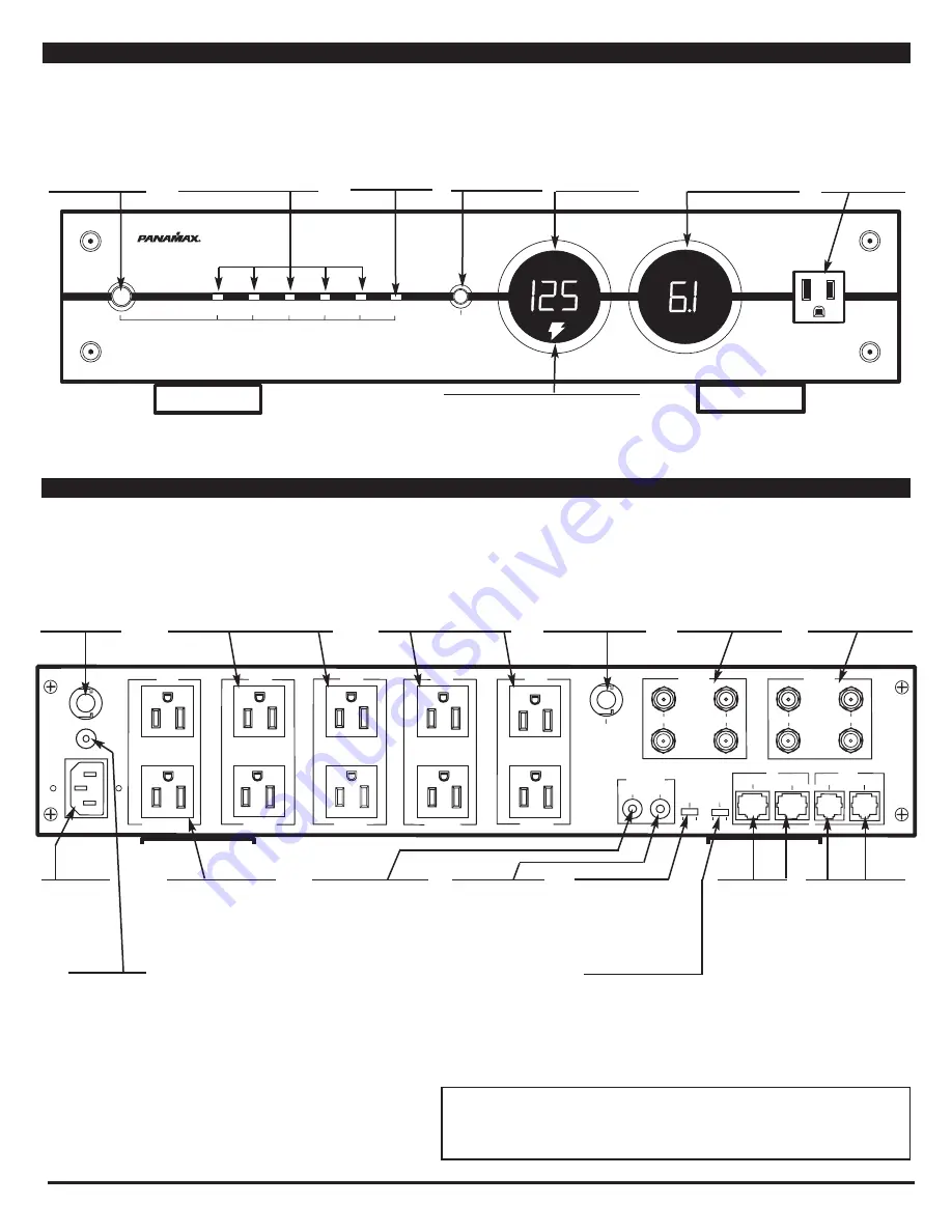
Power Button
Press and hold for 2 sec-
onds to turn Outlet Banks
3, 4 and 5 ON or OFF. This
switch is bypassed if the
rear panel DC Trigger
input is being used.
Power LEDs
Indicates the status of the rear panel
outlets. LEDs for each outlet bank
will be lit when the outlets are turned
ON. They will flash during the start-
up and shutdown process.
Main Circuit
Breaker
Automatically opens
when the current load
is greater than 15
Amps. Push to reset.
Ground Lug
Provides a common
grounding point for
equipment with sep-
arate ground leads.
Main Power
Must be plugged
into a properly
wired & ground-
ed 3-wire outlet
Wiring OK LED
Normally On. Indicates
that the wall outlet is
properly grounded and
Line/Neutral polarity is
correct.
Meter Dimmer
Pushbutton control for
meter LED brightness.
Cycles between Off,
Low, Medium and High.
Unsafe Voltage Indicator
Normally Off. Flashes to indicate that the incoming
line voltage is unsafe and the unit has disconnected
the power to protect your equipment.
Isolation Transformer
Circuit Breaker
Automatically opens when
the combined current load
for Outlet Banks 3 and 4 is
greater than 4 Amps. Push
to reset.
Ammeter
Shows the actual current
draw (0-15A) of all your con-
nected components, giving a
visual reference as to how
your system is functioning
under a variety of conditions.
Convenience
Outlet
Provides a quick con-
venient way to plug in
components such as
camcorders and video
game systems.
Outlet Banks 1 & 2
Two always on outlets
per bank.
Power will only be turned off under
a fault condition. (See specifica-
tions for over-voltage and under-
voltage thresholds) Power for each
bank is cleaned by a four-stage bal-
anced Pi filter. Banks 1 and 2 are
noise isolated from each other as
well as all other outlet banks.
Outlet Banks 3 & 4
Two switched outlets
per bank. ON/OFF
status is controlled by the front panel
Power Button or the DC Trigger input. They
will turn on immediately and turn off after
10 seconds. EMI/RFI noise filtration is pro-
vided by the Isolation Transformer in con-
junction with a three-stage balanced Pi fil-
ter. Banks 3 and 4 are noise isolated from
each other as well as all other outlet banks.
Outlet Bank 5
Two switched, high current
outlets
controlled by the
front panel Power Button or
the DC Trigger input. Bank 5
has a 5 second turn on delay
and turns off immediately.
The High Current outlets pro-
vide power from a low
impedance noise filtration
circuit that does not limit the
current to your equipment.
Its output is noise isolated
from all of the other outlet
banks.
Voltage Sense
Trigger Input
3.5mm (1/8”) Mini-Plug jack.
Connect to a remote trigger
device that uses a DC output to
trigger a startup/shutdown
sequence. This bypasses the
front panel power switch.
Important, Please Note:
The
unit needs to be plugged in,
and in the powered OFF state
before inserting the DC input
trigger mini-plug.
Voltage Sense
Trigger Output
3.5mm (1/8”) Mini-Plug
jack. Connecting a trig-
ger wire to the Voltage
Sense Output jack will
allow the input signal to
pass through the MAX®
5500-EX to control the
startup/shutdown of an
additional device.
High Current Outlets
Delay Switch For
Outlet Bank 5
Allows the outlet bank to
be set as
“Always ON”
or
with a 5 second turn-on
delay
Isolation Transformer
Outlets Delay Switch For
Outlet Banks 3 & 4
Allows the outlet banks to be
set as
“Always ON”
or with a 5
second turn-off delay
LAN Jacks
Protection circuits
for 10/100 baseT
Ethernet lines.
Incoming LAN line
MUST
be plugged
into the
LINE
jack.
Patch cord to the
equipment
MUST
be plugged into
the
EQUIP
jacks.
Phone Jacks
Protection circuits for
standard telephone or pay-
per-view lines. Phone cir-
cuit is auto-resetting.
Incoming phone cord
MUST
be plugged into the
LINE
jack. Patch cords to
the equipment (satellite
receiver, digital video
recorder, telephone, etc.)
MUST
be plugged into the
EQUIP
jacks.
Satellite TV
Coax Jacks
Bidirectional protection cir-
cuit optimized for satellite
TV signal lines. Do not use
for cable TV, off-air anten-
nas and cable modems.
Cable TV Coax Jacks
Bidirectional protection
circuit optimized for cable
TV, off-air antennas and
cable modem signal lines.
Do not use for Satellite TV.
Voltmeter
Digital LED voltmeter
indicates incoming
line voltages between
90–140VAC.
M5500-EX Back Panel Connection Features
M5500-EX Front Panel Features
Note to CATV Installers:
This reminder is provided to call attention to Article 820-40 of the NEC. That article provides
specific guidelines for proper grounding. It specifies that the cable ground shall be connect-
ed to the grounding system of the building and as close to the point of entry as practical.


