background image

MAX PRO-SERIES Communication/Configuration Specifications (continued)

USA & Canada (800) 472-5555  •  (707) 283-5900  •  Fax (707) 283-5901

13

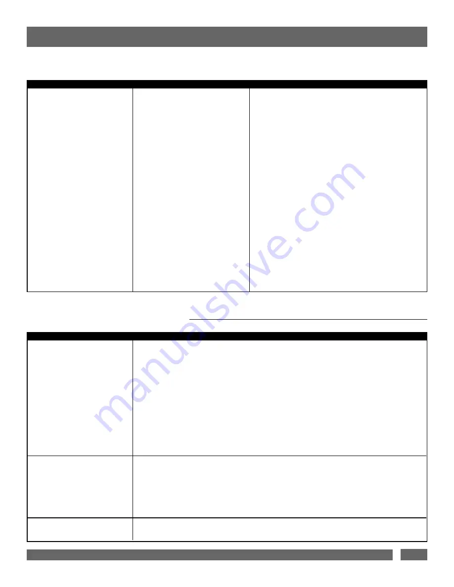
Request a list of all configurable 
parameters and current settings.

2.8

?LIST_CONFIG<CR>

$TRIGGER FOR 1 = 

triggersource

<CR>

$TRIGGER FOR 2 = triggersource<CR>

$TRIGGER FOR 3 =

triggersource

<CR>

$TRIGGER FOR 4 = 

triggersource

<CR>

$TRIGGER FOR HC1 = 

triggersource

<CR>

$TRIGGER FOR HC2 = 

triggersource

<CR>

$TRIGGER FOR TRIGOUT = 

triggersource

<CR>

$DELAY FOR 1 = 

ondelay  offdelay

<CR>

$DELAY FOR 2 = 

ondelay  offdelay

<CR>

$DELAY FOR 3 = 

ondelay  offdelay

<CR>

$DELAY FOR 4 = 

ondelay  offdelay

<CR>

$DELAY FOR HC1 = 

ondelay  offdelay

<CR>

$DELAY FOR HC2 = 

ondelay  offdelay

<CR>

$DELAY FOR TRIGOUT = 

ondelay  offdelay

<CR>

$BRIGHTNESS = x<CR> 

$FEEDBACK = x<CR>

$LINEFEED = x<CR>

QUERIES 

(continued)

RESPONSES AND WARNING MESSAGES

If unsolicited feedback is enabled, the following warning messages will be transmitted under the conditions outlined in their description.  

Query                                                      Description                                                            Response

Condition                                               Message

$BANK1 = 

status

<CR>

$BANK2 = 

status

<CR>

$BANK3 = 

status

<CR>

$BANK4 = 

status

<CR>

$HC1 = 

status

<CR>

$HC2 = 

status

<CR>

$TRIGOUT = 

status

<CR>

status

= { ON, OFF } 

if front panel button is ON, $BUTTON = ON<CR>

if front panel button is OFF, $BUTTON = OFF<CR>

if input trigger is ON, $TRIGIN = ON<CR>

if trigger input is OFF, $TRIGIN = OFF<CR>

$PWR = OVERVOLTAGE<CR>

Outlet bank or trigger output
changes (on/off) state.

When either the front panel but-
ton or input trigger (on/off) sta-
tus changes, a status message is
sent to the controller.

Input voltage rises above the
overvoltage threshold.

3.1

3.2

3.3

Summary of Contents for MAX 7500-PRO

Page 1: ...utilized during the develop ment of this model The MAX 7500 PRO has been specifically engi neered to enhance the performance and life expectancy of high end Audio Video entertain ment gear The combin...

Page 2: ...ection 7 Automatic Over Under Voltage Protection 7 Technical Specifications 8 RS 232 Command Specification 9 10 11 12 13 Troubleshooting 14 Warranties 15 TABLE OF CONTENTS USA Canada 800 472 5555 707...

Page 3: ...one wider than the other A grounding type plug has two blades and a third grounding prong The wide blade or the third prong are provided for your safety If the provided plug does not fit into your ou...

Page 4: ...l modes Cross contamination between your components is also eliminated with this design High Current Components One bank of individually switched outlets bank 5 specifically addresses the unique power...

Page 5: ...RESET TEST RESET TEST TEST RESET 6 AMP MAX PVR TiVo SUBWOOFER HOME AUTOMATION CONTROL AUDIO VIDEO RECEIVER AMPLIFIER PHONE JACK DUAL LNB SATELLITE DISH AUDIO VIDEO RECEIVER PVR TiVo SATELLITE RECEIVER...

Page 6: ...11 DC Trigger Input 3 5mm 1 8 Mini Plug jack Connect to a remote trigger device that uses a DC voltage signal to initiate a startup shut down sequence 12 DC Trigger Output 3 5mm 1 8 Mini Plug jack The...

Page 7: ...tom startup shutdown Bank 5 High Current Outlets The two individually switched high current outlets allow amplifiers and powered subwoofers to work to their full potential When the movie thunders with...

Page 8: ...rigger is not built in Output Trigger The MAX 7500 Pro generates its own 12VDC remote signal to control other components In its default state this output turns ON ten seconds after the Input Trigger r...

Page 9: ...io video equipment must be connected to the EQUIP jack USA Canada 800 472 5555 707 283 5900 Fax 707 283 5901 7 RJ 45 1 2 3 4 5 6 7 8 LAN TEL AC Surge Protection When the MAX 7500 Pro is subjected to a...

Page 10: ...6 mA 3V 58mA 24V DC TRIGGER INPUT Voltage 5VDC Current 100mA USB LIGHT Voltage 12V Current 400 mA Short circuit protection Yes Delay on output 10 seconds DC TRIGGER OUTPUT CABLE TV CIRCUIT TELEPHONE C...

Page 11: ...he status of the front panel button to OFF Turns on all outlets Turn on is immediate with no delay Terminates any running turn on or turn off sequence Overrides the DC trigger input Changes the status...

Page 12: ...CR bank 1 2 3 4 HC1 HC2 TRIGOUT triggersource NONE BUTTON TRIGIN where NONE Outlet bank is always ON trigger output is OFF RS232 only BUTTON Trigger on front panel button TRIGIN Trigger on DC input tr...

Page 13: ...meter brightness feed back mode linefeed mode to their original factory settings listed below Resets the configuration below TRIGGER FOR 1 BUTTON TRIGGER FOR 2 BUTTON TRIGGER FOR 3 BUTTON TRIGGER FOR...

Page 14: ...igger input is OFF TRIGIN OFF CR BANK1 status CR BANK2 status CR BANK3 status CR BANK4 status CR HC1 status CR HC2 status CR TRIGOUT status CR status ON OFF if input voltage is within limits PWR NORMA...

Page 15: ...OR TRIGOUT ondelay offdelay CR BRIGHTNESS x CR FEEDBACK x CR LINEFEED x CR QUERIES continued RESPONSES AND WARNING MESSAGES If unsolicited feedback is enabled the following warning messages will be tr...

Page 16: ...he buzz is to find the source of the distur bance most likely a quartz lamp and plug it into a different branch circuit Panamax Technical Support will be glad to help you if you have any questions abo...

Page 17: ...on before dis connecting your equipment 4 DETERMINATION OF FAILURE Panamax will evaluate the protector for surge damage The Panamax protector must show signs of surge damage or must be performing outs...

Reviews: