HD
SATELLITE
SATELLITE 1
SATELLITE 2
HD
CATV / ANT
CABLE 1
CABLE 2
PHONE LINE
TO EQUIP 2
PHONE LINE
TO EQUIP 1
PHONE
LINE IN
LAN
LINE IN
LAN
TO EQUIP
USB LIGHT
UTPUT
V/400mA
BANK 2 BANK 3 BANK 4 5 HC 1 5 HC 2
SWITCH
SETTINGS
CUSTOM
SETTINGS
DELAY
ALWAYS
ON
DELAY
ALWAYS
ON
DELAY
ALWAYS
ON
DELAY
ALWAYS
ON
DELAY
ALWAYS
ON
5VDC/100mA
R
FEATURE DETAILS
(continued)
Satellite TV:
Satellite dish LNBs can require up to 24 volts to
operate and utilize the frequency range of 950 MHz
to 2.2 GHz. The clamping level of the MAX 7500-
Pro's satellite protection circuitry is 25 volts, just 3
volts above the maximum operating voltage. The
circuitry is shielded to prevent interference and has
been optimized to have less than 1dB of signal loss
throughout the entire 950 MHz to 2.2 GHz range.
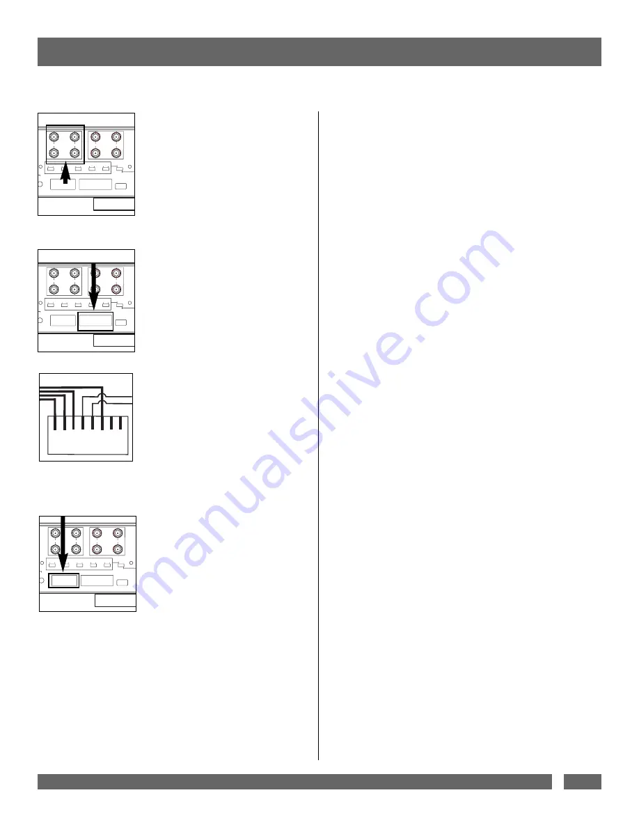
Telephone Protection:
This unit provides protection to one telephone Line
In (RJ-11), and incorporates a built-in splitter to
Equipment 1 (RJ-11) and Equipment 2 (RJ-11).
Satellite TV receivers and DVR’s (digital video
recorders) require telephone line connections for
subscription services. The MAX 7500-Pro provides
surge protection for this line. The circuitry utilizes
auto-resetting PTCRs and solid-state SIDACtors for
reliability and unsurpassed protection. The clamping
level of the MAX 7500-Pro's telephone protector is
260 volts. This will allow typical ring voltage (90-
130VAC) and operating battery voltage (-48DC) to
pass through the circuit and still protect the modem
in your satellite receiver or DVR from damage.
To protect a telephone jack:
Connect a telephone cable from the wall jack outlet
to the Line In (RJ-11) jack on the MAX 7500-Pro,
then connect a second telephone cable from either
the Equipment 1 (RJ-11) or Equipment 2 (RJ-11)
jack on the MAX 7500-Pro to the equipment’s phone
jack. An RJ-11 connector with a minimum of 26
AWG conductors needs to be used when connecting
to the telephone jacks.
To protect a LAN line:
Connect a network cable from the wall jack to the
MAX 7500-Pro Line In
(RJ-45) jack, then connect a second cable from the
Equipment (RJ-45) jack on the MAX 7500-Pro to the
network device jack.
Please Note:
The protection circuitry will not work if the phone
lines are reversed. The incoming phone cable must
be connected to the
“LINE”
jack and the cable to the
audio/video equipment must be connected to the
“EQUIP”
jack.
USA & Canada (800) 472-5555 • (707) 283-5900 • Fax (707) 283-5901
7
RJ-45
1 2 3 4 5 6 7 8
LAN
TEL
AC Surge Protection:
When the MAX 7500-Pro is subjected to a high volt-
age surge, its voltage output is limited to a safe level
and the high levels of surge current are diverted away
from the connected equipment.
• When subjected to a 6,000V (open circuit voltage)
/ 500A (short circuit current) surge, the MAX 7500-
Pro limits its voltage output to less than 330V peak,
UL’s best rating.
• If the magnitude of the surge is greater than the
capacity of the surge protection components, the
MAX 7500-Pro's Protect or Disconnect Circuitry will
disconnect your equipment in order to protect it.
HD
SATELLITE
SATELLITE 1
SATELLITE 2
HD
CATV / ANT
CABLE 1
CABLE 2
PHONE LINE
TO EQUIP 2
PHONE LINE
TO EQUIP 1
PHONE
LINE IN
LAN
LINE IN
LAN
TO EQUIP
USB LIGHT
UTPUT
V/400mA
BANK 2 BANK 3 BANK 4 5 HC 1 5 HC 2
SWITCH
SETTINGS
CUSTOM
SETTINGS
DELAY
ALWAYS
ON
DELAY
ALWAYS
ON
DELAY
ALWAYS
ON
DELAY
ALWAYS
ON
DELAY
ALWAYS
ON
5VDC/100mA
R
IN OUT
IN OUT OUT
HD
SATELLITE
SATELLITE 1
SATELLITE 2
HD
CATV / ANT
CABLE 1
CABLE 2
PHONE LINE
TO EQUIP 2
PHONE LINE
TO EQUIP 1
PHONE
LINE IN
LAN
LINE IN
LAN
TO EQUIP
USB LIGHT
UTPUT
V/400mA
BANK 2 BANK 3 BANK 4 5 HC 1 5 HC 2
SWITCH
SETTINGS
CUSTOM
SETTINGS
DELAY
ALWAYS
ON
DELAY
ALWAYS
ON
DELAY
ALWAYS
ON
DELAY
ALWAYS
ON
DELAY
ALWAYS
ON
5VDC/100mA
R
Patent Pending Over/Under Voltage
Protection:
The MAX 7500-Pro constantly monitors the AC line
voltage for unsafe voltage conditions such as pro-
longed over voltages and under voltages (brownouts).
These unsafe conditions pose a very dangerous threat
to all electronic equipment within the home. If the
MAX 7500-Pro senses an unsafe power condition, it
will automatically disconnect your equipment from the
power to protect equipment from damage. Once the
voltage returns to a safe level, the MAX 7500-Pro will
automatically reconnect the power.
If the line voltage exceeds the over voltage threshold
or falls below the under voltage threshold, the MAX
7500-Pro will perform the following tasks until line
voltage returns to a safe level:
1.
Voltage reaches an unsafe high
level and the (Automatic Voltage Monitoring)
AVM Circuitry
disconnects.
2.
Voltage reaches a safe level and AVM
Circuitry automatically
reconnects.
3.
Voltage reaches an unsafe low level and
AVM Circuitry
disconnects.
4.
Voltage reaches a safe level and AVM
Circuitry automatically
reconnects.


