P
M8-HT
INSTRUCTIONS -
English
ADDING SIGNAL-LINE MODULES
(Optional):
Some connected equipment may have
more signal-lines than can be protected
by the base unit alone. Panamax offers
a line of add-on signal-line modules
(sold separately) for these situations.
Each module includes installation
instructions and a small rectangular
bracket with a grounding interface. This
bracket replaces the small triangular
wall-mount bracket that comes with the
AC base unit and is needed only when
add-on modules are being installed.
More information can be obtained on
the Panamax website or by calling our
Customer Support Department.
WALL MOUNTING (optional):
1.
Determine the mounting location on
the wall and mark the position for the
top mounting screw.
3.
Place a spacer eyelet on one of the
#6 pan-head screws with the flared end
of the eyelet toward the wall. Drive the
screw into the wall (use the included
drywall anchors for hollow walls) at the
marked location, leaving the eyelet
exposed.
4.
Position the key-hole on the unit's
top mounting bracket over the
eyelet/screw and slide the unit down to
lock the screw-head into the bracket.
5.
Mark the location for the two lower
mounting screws (in the narrow portion
of the key-holes) and drive the screws
into the wall using the other 2 spacer
eyelets like in step #3. The included
drywall anchors should be used for
mounting on hollow walls.
6.
Position the protector over the 3 eye-
lets/screws and slide the unit down to
lock it into place.
7.
Using the above procedure allows
easy removal of the unit by sliding the
unit up to disengage the brackets from
the eyelets/screws.
TROUBLESHOOTING–
If you are having problems with your
surge protector, read this section.
The “Power On/Protection OK” LED
is not lit, there is no AC power to
my equipment, or my equipment
doesn’t turn on.
•
Make sure that the protector is plugged
into a working AC outlet.
•
Check all AC power connections.
•
Make sure that the protector and
connected equipment are turned on.
•
Check to see if the circuit breaker on the
surge protector (combination power
switch/circuit breaker) needs to be reset
(press “ON” to reset).
•
If you still have no power, the protector
may be damaged. Contact Panamax
(website or Customer Support
Department) for replacement.
There is no audio or video for my
TV, stereo or VCR.
•
Check the coaxial connections, making
sure they are correctly and securely
installed.
•
Bypass the coaxial connectors. If your
picture returns, the protector is damaged.
Contact Panamax (website or Customer
Support Department) for replacement.
•
If you still have no picture, a problem
with your cable provider’s signal may
exist.
My fax machine, modem or tele-
phone has AC power but still does
not work.
•
Check to see if your connected equip-
ment is receiving a dial tone.
•
If not, bypass the surge protector’s
phone jacks to see if the protector is dam-
aged.
•
If your dial tone returns, the protector is
damaged. Contact Panamax (website or
Customer Support Department) for
replacement.
•
If you still have no dial tone, a problem
with the phone company’s lines may exist.
The Panamax circuit breaker dis-
connects AC power from the con-
nected equipment.
•
You have exceeded the ampere rating for
your surge protector. As a temporary fix,
disconnect one or more pieces of equip-
ment. Ask your Panamax dealer about
additional Panamax protectors that may
be required.
800-472-5555
www.panamax.com
INS0827 REV. B 6/07
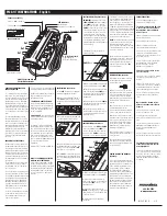
POWER ON
PROTECTION OK
GROUND OK
POWER
O
N
O
FF
LED Indicators
Ground OK LED
Power ON, Protection OK LED
Phone Jacks (RJ-11)
Coax Connectors
Includes Phone Cable (4 ft.)
ON/OFF Power Switch and
Circuit Breaker Combo
6 ft. AC Power Cord
Right Angle with
45 Degree Offset Plug
8 AC Outlets
Two Coax Cables included
Phone Line
OUT
to equipment.
Phone Line
IN
from wall
All of the AC outlets are controlled by the
combination power switch/circuit breaker.
In addition, the PM8-HT has 2 diagnostic
LEDs for maximum safety. They are
designated as follows:
1. POWER ON, PROTECTION OK
–
(green) normally ON; indicates that the
surge protector is functioning properly
and that all connected equipment is pro-
tected. Also indicates that the power
switch is turned ON.
2. GROUND OK
– (green) normally ON;
indicates that the wall outlet is properly
wired and grounded.
The PM8-HT has been designed with
flexibility and expansion in mind. This
unit (protector) will accept add-on signal-
line protection modules in the event that
your installation has more signal-lines
than can be protected with one of the
above units. More information is avail-
able on our website (www.panamax.com)
or from our Customer Support
Department
(800-472-5555; 7:30AM – 4:30PM PST).
NOTE to TV ANTENNA, SATELLITE
DISH and CATV INSTALLERS:
Articles 810.21 and 820.40 of the NEC
provide specific guidelines for proper
grounding, and in particular, specify that
the cable ground shall be connected to
the grounding system of the building,
as close to the point of cable entry as
practical.
PROPERLY CONNECTING YOUR
SURGE PROTECTOR
To completely protect your equipment
from surges, every wire leading into or
out of the equipment you want to protect
must be connected to the appropriate
Panamax surge protector. Damaging
lightning and power surges can enter
your system through any AC power or
signal-line (phone line, grounding wires,
coax cables, modem cables, LAN cables,
etc.) connected to your electronic equip-
ment.
The Panamax $100,000 Connected
Equipment Protection Policy is void if
any wire leading into or out of the equip-
ment is not properly connected to the
appropriate Panamax surge protector(s).
The surge protector must also be
plugged into a properly wired and
grounded outlet. Please see the warran-
ty for details or contact the Panamax
Customer Support Department with
questions.
IMPORTANT SAFETY POINTS
Panamax surge protectors and the con-
nected equipment must be indoors, in a
dry location and in the same building.
Although your Panamax protector is very
durable, its internal components are not
isolated from the environment. Do not
install any Panamax product near heat
emitting appliances such as a radiator or
heat register.
Do not install this product where exces-
sive moisture is present; for example
near a bathtub, sink, pool, basement
floor, fish tank, etc.
It is not uncommon for a building to be
improperly grounded. In order to protect
your equipment, Panamax products must
be plugged into a properly wired and
grounded 3-wire outlet. Additionally,
building wiring and grounding must
conform to applicable NEC (USA) or
CEC (Canada) codes for the Panamax
protection policy to be valid.
Do not use 2-blade adapters or any other
“power strips” with this product. Use
only Panamax extension cords if a
longer cord is required.
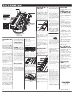
INSTALLATION (AC Power):
1.
Turn
OFF
the power to all equipment
that will be plugged into the unit.
2.
Make sure that the ON/OFF switch is
in the
OFF
position (see figure). Plug
the unit into the wall outlet and then turn
it
ON
.
POWER ON
PROTECTION OK
GROUND OK
4
. Plug the equipment to be protected into
the Panamax unit and one at a time, turn
each piece of connected equipment
ON
and check for correct operation.
5.
Turn
OFF
the unit and all connected
equipment before connecting any signal-
lines or installing any add-on signal line
modules.
3.
Verify that the green “Ground OK” LED
is lit, indicating that the wall outlet is
properly wired and grounded.
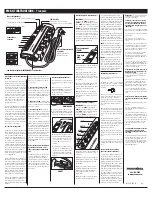
INSTALLATION (Telephone Lines):
IMPORTANT:
Note the position of the
LINE
and
EQUIP
jacks on the Panamax
unit.
LINE
is for the line connection
that comes from the wall or floor jack.
EQUIP
is for the line connection to your
connected equipment. The protection
circuit will only function if connected
properly. Reversed connections will
pass the signal to the connected equip-
ment but will also prevent the protection
circuitry from working and will invali-
date the Panamax Connected Equipment
Protection Policy.
1.
Make sure the Panamax protector and
all connected equipment is turned
OFF
.
2.
Take the incoming telephone line and
plug it into the appropriate
LINE
jack on
the protector. The line should now be
connected between the wall and the
Panamax unit.
3.
Plug a telephone line into the
EQUIP
jack and then plug the other end into the
equipment to be protected.
4.
Turn On the protector and the con-
nected equipment. Verify that each piece
of connected equipment is receiving
power and signal.
The PM8-HT provides protection for
one telephone line.
LINE
(in)
EQUIP
(out)
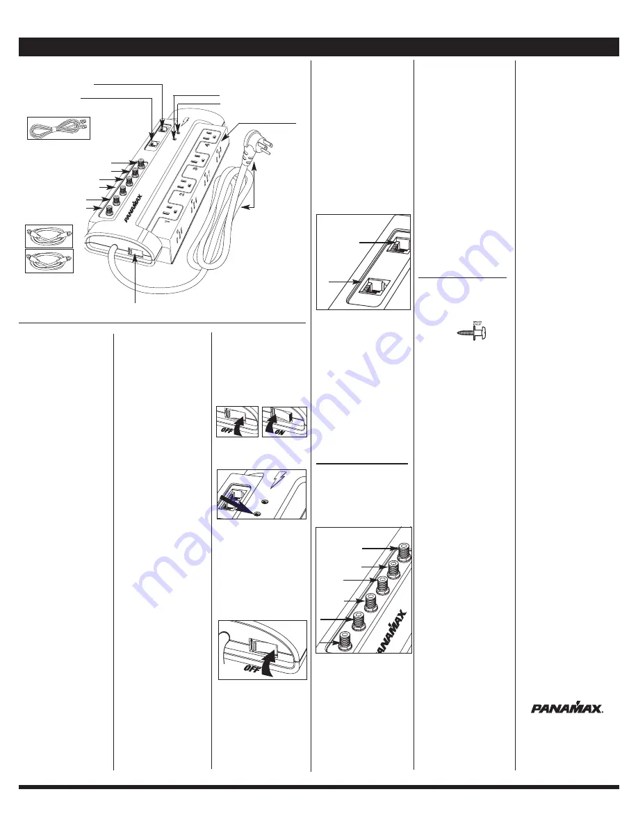
INSTALLATION (Coaxial Lines):
Note the position of the
LINE
and
EQUIP
jacks on the Panamax unit.
LINE
is for
the line connection that comes from the
wall or floor jack.
EQUIP
is for the line
connection to your connected equipment.
The PM8-HT coaxial protection circuits
achieve optimum signal quality from our
new coaxial protectors that have the
smallest signal loss on the market - less
than 0.5dB of attenuation from 0MHz to
2.2GHz. Our upgraded coaxial protection
has been specifically designed to virtually
eliminate signal loss. The clamping level
of 75 volts will meet the demands of both
cable and satellite voltage while minimiz-
ing exposure to spikes and surges.
NOTE:
The CATV/Sat/Antenna protection
circuit in these models is bi-directional
and has been designed to work with
cable TV systems that send pay-per-view
ordering information to the cable compa-
ny over the coaxial line.
Make sure that your equipment is con-
nected to the proper jacks. When used
with diplexers, this protection circuit
must be placed between the diplexer
and the Satellite receiver; it will
not
protect the diplexer.
1.
Make sure the Panamax protector and
all connected equipment is turned
OFF
.
2.
Connect the coaxial cable from the
CATV system, antenna, or Satellite dish to
the appropriate
LINE
connector on the
Panamax protector.
3.
Connect a coaxial cable from the
EQUIP
jack on the protector to appropriate
input jack on your TV, VCR, cable modem
or Satellite receiver.
4.
Repeat steps 2 & 3 for additional
coaxial lines.
Set 1
Set 2
Set 3
Set 1
Set 2
Set 3
LINE
(in)
LINE
(in)
LINE
(in)
EQUIP
(out)
EQUIP
(out)
EQUIP
(out)


