Model CTF878 Startup Guide
37
Chapter 2.
Note:
To enter programming data during operation of the meter, it will be necessary to know which input is
assigned to which process parameter. This information should have been entered in Appendix B, Data
Records
.
The analog inputs, which have an impedance of 118 ohms, should be connected with standard twisted-pair wiring.
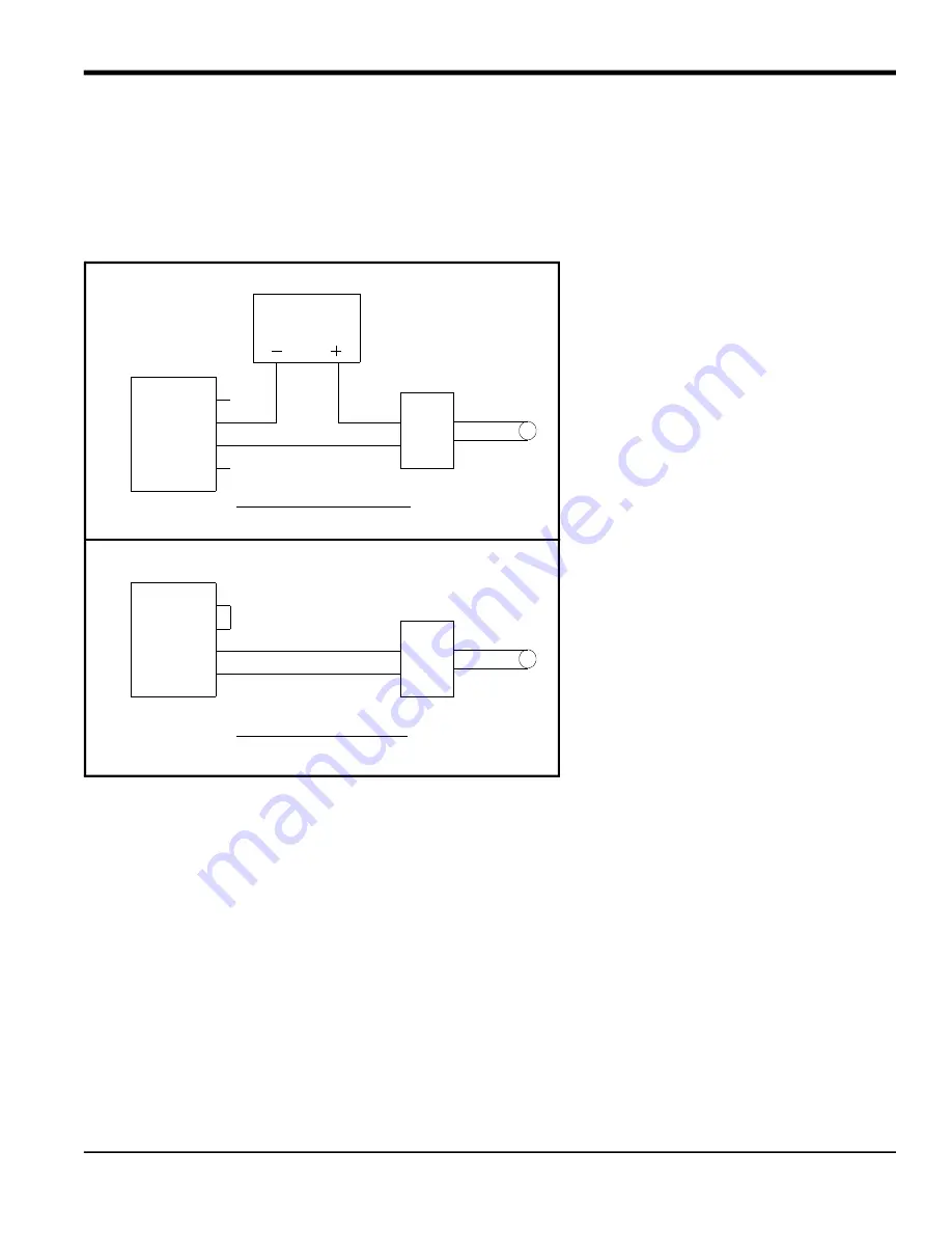
Power to the transmitters may be supplied either by the integral 24 VDC power supply on the analog input card or by
an external power supply. Figure 22 below shows typical wiring diagrams, with and without an external power supply,
for one of the analog inputs.
Figure 22: Analog Input Wiring Diagram
Wire the analog input terminal block in accordance with the pin number assignments shown in Figure 25 on page 40.
If the flowmeter system includes additional transmitters, the CTF878 can accommodate up to three more analog
inputs option cards. These option cards are identical to the temperature/pressure card described above and they
should be wired in the same manner (see Figure 22 on page 37).
The analog inputs on the option card(s) can be calibrated with the CTF878’s built-in analog outputs. However, be
certain that the analog outputs have been calibrated first. See Chapter 1,
Calibration, in the Service Manual for the
appropriate procedures.
2.1.14.3
Wiring a Totalizer/Frequency Outputs Option Card
The CTF878 can accommodate up to four totalizer/frequency outputs option cards. Each totalizer/frequency outputs
option card provides four outputs (designated as A, B, C, and D) that can be used as either totalizer or frequency
outputs.
Each totalizer/frequency output requires two wires. Wire this terminal block in accordance with the pin number
assignments shown in Figure 25 on page 40. Figure 23 below shows sample wiring diagrams of a totalizer output
circuit and a frequency output circuit.
PIN #
(RTN)
(INLO)
(INHI)
(+24V)
4
3
2
1
Analog Input
– OUT
+ IN
Transmitter
SENSOR
24VDC
POWER SUPPLY
With External Power Supply
With Internal Power Supply
Analog Input
2
1
3
4
PIN #
(+24V)
(INLO)
(INHI)
(RTN)
Transmitter
+ IN
– OUT
SENSOR
Jumper
Summary of Contents for CTF878
Page 1: ...panametrics com Flow 910 254U Rev A AUG 2021 Model CTF878 Clamp On Tag Flowmeter Startup Guide...
Page 2: ......
Page 4: ...ii no content intended for this page...
Page 6: ...Warranty iv Model CTF878 Startup Guide no content intended for this page...
Page 8: ...Contents vi Model CTF878 Startup Guide...
Page 76: ...Model CTF878 Startup Guide 68...
Page 96: ...Appendix A 88 Model CTF878 Startup Guide...
Page 99: ...Model CTF878 Startup Guide 91 Appendix B 9 21 10 22 11 23 12 24...
Page 100: ...Appendix B 92 Model CTF878 Startup Guide...
Page 104: ...Index 96 Doc Tittle Manual Type...
Page 106: ......
Page 107: ......


