3.3.4 Fuel configuration
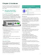
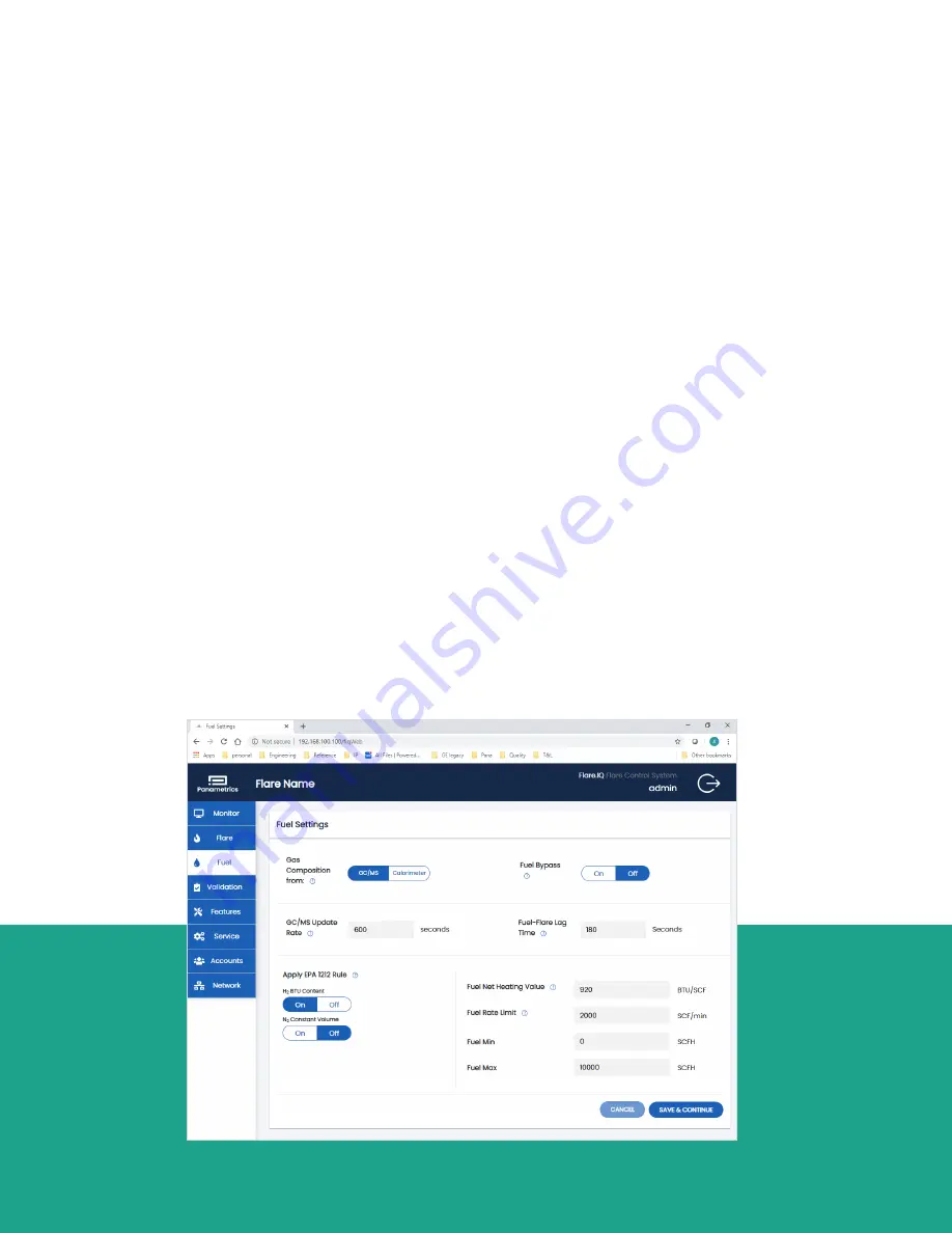
As shown in figure 21 this page enables setting the
following flare (supplemental) fuel specific parameters:
• Choice of online flare gas analyzer – GC/calorimeter
• Time interval between readings from GC/MS
• Minimum allowed fuel flow
• Maximum allowed fuel flow
• Lag time between fuel flow change and flare
meter response
• Action threshold for changes in steam or
fuel demand
• Nominal fuel net heating value (natural gas
in this example)
The bottom left of the fuel page has two special
configuration parameters:
1. Choice of NHV for H2 between 275 BTU/SCF and
1212 BTU/SCF (apply EPA 1212 rule)
2. Choice of constant N
2
volumetric flow (i.e., N
2
mole
fraction inversely proportional to total flare gas flow)
or constant N
2
mole fraction
In addition to tooltips, detailed information on the purpose
of each of the above settings as they apply to your flare
installation along with in-depth instructions on how to
determine the correct values to enter can be obtained
from your Panametrics field service engineer.
3.3.5 Monitor overview
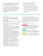
After all configuration steps are complete, the monitor
overview is displayed. This screen provides a real-time
readout of essential data being sent to the flare.IQ, and
the results the flare.IQ has calculated. Displayed data is
organized in ‘panes’ as follows:
• The heading bar displays the configured flare name
or tag, the Modbus connection status, and the user
currently logged in. A running time display indicates
updates of the data below.
• The system readouts pane shows the net heating
value (NHV) actual. This is the calculated energy
content at the flare tip, as determined by the gas
composition and energy content derived from the
vent/flare gas flowmeter measurements. NHV
actual
must remain above a critical value of 270 BTU/SCF
for EPA compliance under the MACT rules.
• This pane also shows the fuel demand and
steam or air demand. These are the quantities of
supplemental fuel and assist flow calculated by
the flare.IQ for optimal operation. It is these values
that the controlling DCS should use as setpoints
for the fuel flow, steam flow, or air flow.
• The flare pane displays the critical flare measurements
as captured by the DCS and sent to the flare.IQ. Use this
to verify that the data obtained from the flare flowmeter,
temperature, and pressure sensors is being reliably
transferred from the DCS to the flare.IQ.
Figure 21: Fuel settings configuration page
23
Summary of Contents for flare.IQ Generation 2
Page 1: ...flare IQ Generation 2 Operation and maintenance manual...
Page 2: ...2...
Page 3: ...flare IQ Generation 2 Operation and maintenance manual 910 350 rev A June 2020 3...
Page 4: ...no content intended for this page 4...
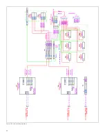
Page 38: ...Figure 30 System wiring diagram 38...
Page 48: ...48...


